Outline of Piping Design: Basic Elements for Industrial Plants
In my two decades of experience navigating complex brownfield and greenfield projects, I have learned that the integrity of a process plant rests entirely on the precision of its piping design. It is not merely about connecting two points with a pipe; it is about managing thermal expansion, pressure drops, and material compatibility under extreme operating conditions.
This guide serves as a foundational roadmap for engineers tasked with developing robust piping systems. We will dissect the essential elements—from initial line sizing to the final stress analysis—that ensure your facility operates within safe, code-compliant parameters for its entire design life.
Key Takeaways for Piping Engineers:
- Mastering the hierarchy of ASME B31.3 and API standards.
- Understanding the critical relationship between fluid velocity and pipe diameter.
- Implementing effective support strategies to mitigate vibration and thermal stress.
- Ensuring material selection aligns with corrosive and high-temperature service requirements.
Technical Outline of Piping Design: Basic Elements
Piping Design Engineering: The technical discipline of calculating, routing, and specifying piping systems to ensure structural integrity and fluid containment under specified pressure and temperature ratings.
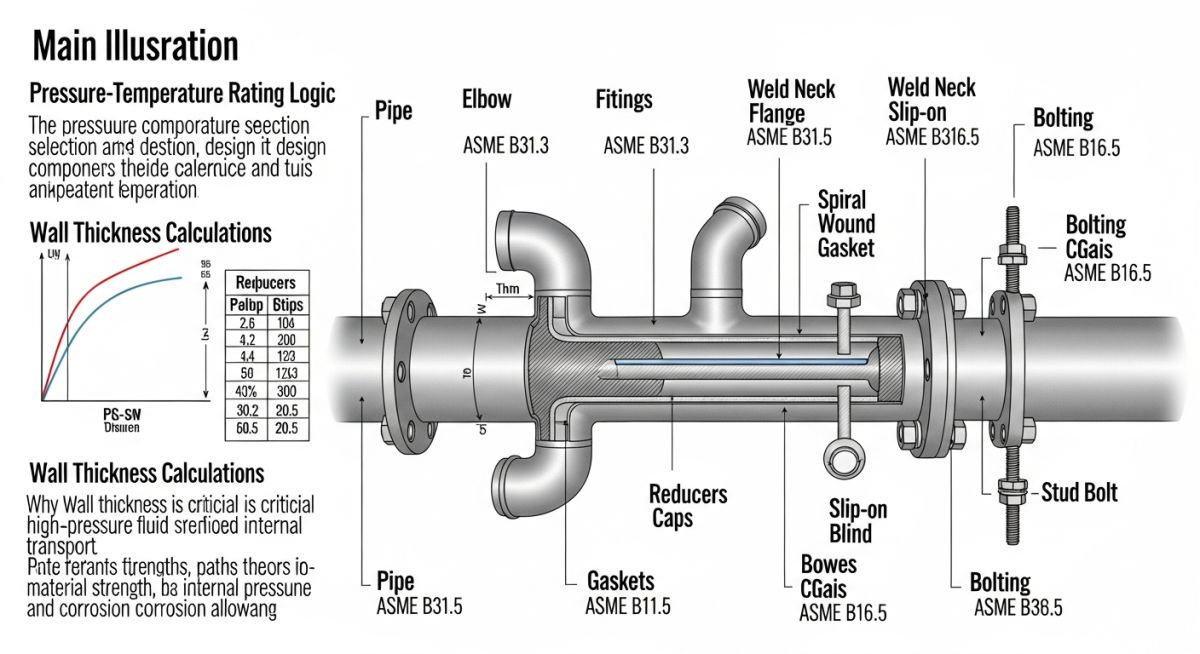
The core of any piping design project begins with the fluid property analysis. Before a single line is drawn, we must determine the mass flow rate, density, and viscosity of the process medium. These parameters dictate the internal diameter (ID) of the pipe, which is calculated to maintain an optimal velocity—typically 3 to 5 meters per second for liquids to prevent erosion and pressure surges.
Once the diameter is established, we select the pipe schedule based on the pressure-temperature rating. According to ASME B31.3, the required wall thickness is determined by the formula: t = (P * D) / (2 * (S * E + P * Y)) + C. Here, P represents internal design pressure, D is the outside diameter, S is the allowable stress of the material, E is the quality factor, and C is the corrosion allowance. I always emphasize that the corrosion allowance must be calculated based on the expected service life of the plant, not just the initial startup phase.
Field Warning: Material Selection Errors
Never assume that standard carbon steel (A106 Gr. B) is sufficient for all process lines. In my experience, failing to account for trace contaminants like H2S or chlorides leads to premature stress corrosion cracking. Always verify the NACE MR0175 requirements for sour service environments before finalizing your piping material specifications.
Layout design is the next critical phase. We must ensure that the piping configuration allows for thermal expansion without overstressing the equipment nozzles. This involves the strategic placement of expansion loops, anchors, and guides. If the thermal growth exceeds the allowable nozzle load of a pump or compressor, the design must incorporate flexible elements or re-routed piping paths to absorb the movement.
Finally, we perform a stress analysis using software like CAESAR II. We evaluate the system against sustained loads (pressure and weight), thermal expansion, and occasional loads (wind, seismic, or water hammer). If the calculated stress exceeds the allowable limits defined in the code, we must adjust the support span or pipe wall thickness to bring the system back into compliance.
Piping System Optimization: The strategic balancing of material costs, maintenance accessibility, and structural reliability to achieve a lifecycle-efficient plant design.
Advantages
- Standardized components ensure global availability and interchangeability.
- Rigid piping systems provide high resistance to external mechanical impacts.
- Predictable performance under steady-state pressure and temperature conditions.
- Well-documented design codes simplify regulatory approval and safety audits.
Disadvantages
- High initial capital expenditure for high-alloy materials in corrosive service.
- Complex thermal expansion management requires significant plot space for loops.
- Susceptibility to fatigue failure if vibration sources are not properly isolated.
- Extensive field welding requirements increase the risk of localized defects.
Industrial Piping Implementation: The practical application of fluid transport principles across diverse sectors to ensure safe, efficient, and code-compliant process operations.
High-Pressure Steam Distribution
In power generation, piping design must account for extreme thermal cycling and high-velocity steam flow. We utilize high-chrome alloy steels and specialized spring hangers to accommodate significant pipe movement while maintaining nozzle integrity at the turbine interface.
Cryogenic Liquefied Natural Gas (LNG) Processing
LNG facilities require materials capable of maintaining ductility at temperatures as low as minus 162 degrees Celsius. The design focuses on vacuum-jacketed piping and specialized bellows to minimize heat ingress and prevent brittle fracture of the pressure boundary.
Corrosive Chemical Feed Systems
For aggressive chemical processing, we prioritize non-metallic piping or lined steel systems to prevent wall thinning. The design must include secondary containment and rigorous leak detection protocols to protect personnel and the surrounding environment from hazardous releases.
High-Velocity Slurry Transport
Mining and mineral processing plants utilize thick-walled piping with internal wear-resistant linings to handle abrasive slurries. The layout emphasizes large-radius bends and minimal fittings to reduce turbulence and extend the service life of the piping system.
Selecting the correct pipe schedule is a fundamental task in piping design, directly impacting the structural integrity and safety of the entire process unit. My experience dictates that engineers must balance fluid velocity, corrosion allowance, and pressure containment requirements against the economic constraints of the project. The following table provides a reference for common carbon steel pipe dimensions, which are governed by ASME B36.10M standards.
When reviewing these values, remember that the nominal pipe size (NPS) does not represent the actual outside diameter for sizes above 12 inches. Instead, the outside diameter remains constant while the wall thickness increases with the schedule number. Always verify the specific pressure-temperature ratings using ASME B31.3 to ensure your selected material grade can withstand the peak operating conditions of your specific system.
| NPS (Inches) | Outside Diameter (mm) | Sch 40 Thickness (mm) | Sch 80 Thickness (mm) |
|---|---|---|---|
| 1 | 33.4 | 3.38 | 4.55 |
| 2 | 60.3 | 3.91 | 5.54 |
| 4 | 114.3 | 6.02 | 8.56 |
Effective piping design requires a rigorous mapping of physical parameters to international engineering codes. This matrix serves as a high-level guide for aligning system requirements with the appropriate regulatory frameworks. In my practice, I have found that maintaining a clear traceability matrix between fluid properties and material specifications prevents costly procurement errors and ensures long-term plant reliability.
The entities listed below represent the core pillars of piping documentation. Each component must be cross-referenced against the project’s Piping Material Specification (PMS) and the relevant ASME code sections. By standardizing these inputs, engineering teams can streamline the review process and reduce the likelihood of field-based design modifications during the construction phase.
| Entity | Primary Standard | Key Parameter |
|---|---|---|
| Pressure Piping | ASME B31.3 | Design Pressure/Temp |
| Flange Dimensions | ASME B16.5 | Bolt Circle Diameter |
| Pipe Dimensions | ASME B36.10M | Wall Thickness |
Before finalizing any piping design, a comprehensive site verification is mandatory to ensure that the digital model aligns with the physical reality of the plant environment. I have seen too many projects suffer from interference issues because the design team relied solely on outdated P&IDs or incomplete laser scans. This checklist provides a structured approach to validating your design against site conditions.
- Clearance Verification: Confirm that all maintenance access paths meet the minimum requirements defined in OSHA standards.
- Support Integrity: Verify that existing structural steel can handle the calculated dead weight and thermal loads of the new piping run.
- Tie-in Accuracy: Physically measure the location of all existing tie-in points to ensure they match the isometric drawings within a 5mm tolerance.
- Drainage Slope: Ensure that gravity-fed lines maintain the required slope as specified in the project process flow diagrams.
- Instrument Access: Confirm that all control valves and flow meters are accessible for calibration and emergency manual operation.
Always document these findings in a formal site survey report. If discrepancies are found, they must be reconciled through a formal Management of Change (MOC) process before proceeding with fabrication or installation. This rigorous verification step is the most effective way to minimize field rework and ensure the safety of the operating personnel.
Problem: Thermal Expansion Failure in High-Pressure Steam Line
A high-pressure steam line experienced repeated flange leaks at a critical junction due to excessive thermal growth that was not properly accounted for in the initial piping design.
- Inadequate flexibility analysis for the high-temperature operating cycle.
- Rigid pipe supports preventing necessary thermal expansion.
- Incorrect selection of gasket material for the specific steam temperature.
- Lack of expansion loops in the long straight pipe runs.
Outcome: Successful Remediation and System Stabilization
The system was successfully stabilized by implementing a comprehensive redesign that prioritized thermal flexibility and structural support optimization.
- Installation of two engineered expansion loops to absorb thermal growth.
- Replacement of rigid supports with spring hangers to allow for vertical movement.
- Upgrade to spiral-wound gaskets compliant with ASME B16.20.
- Reduction in flange leakage incidents to zero over a 24-month period.
My recommendation for similar scenarios is to always perform a formal pipe stress analysis using software like CAESAR II for any system operating above 150 degrees Celsius. Relying on “rule of thumb” design for high-energy systems is a recipe for failure; analytical validation is the only way to guarantee long-term integrity.
How do I determine the correct pipe schedule for my application?
Determining the pipe schedule is a multi-step process that begins with identifying the design pressure and temperature as defined in your process data sheets. You must then reference the ASME B31.3 pressure-temperature rating tables for the specific material grade you are using.
- Calculate the minimum required wall thickness using the Barlow formula or the specific equations provided in the code.
- Add the required corrosion allowance to the calculated minimum thickness.
- Select the next standard pipe schedule from ASME B36.10M that provides a wall thickness greater than or equal to your calculated value.
- Verify that the selected schedule meets the structural requirements for the pipe span between supports.
What is the difference between NPS and DN?
NPS stands for Nominal Pipe Size, which is the North American standard for designating pipe dimensions, while DN stands for Diameter Nominal, the metric equivalent used internationally. While they are often used interchangeably in casual conversation, they represent different sizing systems that can lead to compatibility issues if not carefully managed.
- NPS is a dimensionless designator that relates to the approximate inside diameter for smaller pipes and the outside diameter for larger pipes.
- DN is a metric designation that corresponds to the approximate outside diameter in millimeters.
- Always check the specific project specification to determine which system is the primary design basis.
- When mixing components from different regions, ensure that the flange ratings and bolt patterns are compatible according to ASME B16.5 or ISO standards.
Why is pipe stress analysis important?
Pipe stress analysis is the critical engineering process used to ensure that a piping system can safely withstand all internal and external loads without exceeding the allowable stress limits of the material. Without this analysis, systems are prone to fatigue, buckling, and catastrophic failure under thermal or seismic conditions.
- It evaluates the impact of thermal expansion and contraction on equipment nozzles.
- It ensures that pipe supports are correctly placed to prevent sagging and vibration.
- It validates that the system complies with the stress range requirements of ASME B31.3.
- It identifies potential interference points that could lead to structural damage during operation.
How do I select the right gasket material?
Gasket selection is a balance between chemical compatibility, temperature resistance, and the ability to maintain a seal under varying pressure conditions. I always recommend consulting the manufacturer’s chemical resistance chart before finalizing your choice for any process fluid.
- For high-temperature steam, spiral-wound gaskets with graphite filler are the industry standard.
- For corrosive chemical services, PTFE-based gaskets are often preferred due to their inert nature.
- Ensure the gasket material is compatible with the flange face finish to prevent leakage.
- Always verify that the gasket meets the requirements of ASME B16.21 for non-metallic or ASME B16.20 for metallic gaskets.
What are the requirements for pipe supports?
Pipe supports are designed to carry the weight of the pipe, the fluid, and any insulation, while also controlling thermal movement and vibration. The design of these supports must be integrated into the overall piping layout to ensure that no excessive loads are transferred to sensitive equipment.
- Supports must be spaced according to the maximum allowable span tables to prevent excessive deflection.
- Spring hangers are required in areas where vertical thermal movement is significant.
- Anchors must be placed strategically to direct thermal expansion toward expansion loops or joints.
- All support designs should comply with MSS SP-58 standards for materials and design.
How do I handle piping in seismic zones?
Piping design in seismic zones requires additional considerations to ensure the system remains intact during a seismic event. This involves calculating the lateral forces acting on the piping and providing adequate restraint without over-constraining the system.
- Use seismic restraints such as snubbers or sway braces to limit pipe movement.
- Ensure that flexible connections are installed at building interfaces to accommodate differential movement.
- Perform a dynamic analysis to determine the natural frequency of the piping system.
- Follow the guidelines provided in ASCE 7 for seismic design requirements in industrial facilities.
📚 Recommended Resources: Piping Design
Read these Guides
🎓 Advanced Training


Complete Course on
Piping Engineering
Check Now
Key Features
- 125+ Hours Content
- 500+ Recorded Lectures
- 20+ Years Exp.
- Lifetime Access
Coverage
- Codes & Standards
- Layouts & Design
- Material Eng.
- Stress Analysis
