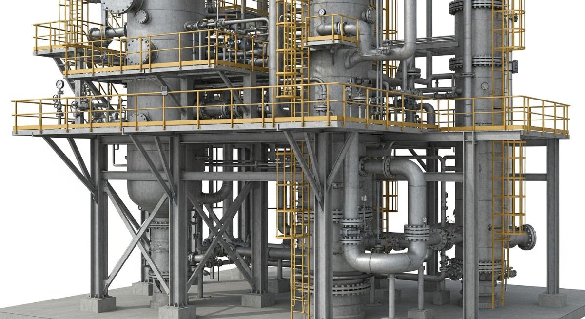
Column Piping Design Considerations for Vertical Process Towers
In my 20-plus years of executing piping layouts for global petrochemical and refining facilities, I have found that vertical columns—often called tall towers—present some of the most complex spatial and structural challenges an engineer will ever face. Unlike horizontal vessels, a vertical column is a dynamic, living structure. It expands significantly when heated, sways under wind and seismic loads, and demands safe, multi-level operator access.
When I review a model, I do not just look at the pipe routing; I look at how the piping interacts with the vessel shell, the internal trays, the structural platforms, and the maintenance access ways. A failure to coordinate these elements early in the design phase leads to costly field re-work, compromised structural integrity, and operational hazards.
Key Engineering Takeaways
- Understand the critical relationship between internal tray layouts and external nozzle orientations.
- Master the management of differential thermal expansion between the vessel shell and vertical piping runs.
- Design integrated platform systems that provide safe access to instruments, valves, and manways without clashing with piping.
- Apply rigorous stress analysis to prevent excessive nozzle loading under wind, seismic, and thermal conditions.
Mastering Column Piping Design for Tall Process Towers
[Tower Piping Layout]: The strategic arrangement of vertical lines, utility headers, and instrument connections to minimize thermal stress and optimize operator access under ASME B31.3 guidelines.
To execute a flawless layout, we must first understand the internal mechanics of the column. Process towers utilize internal trays or packing to facilitate mass transfer between liquid and vapor phases. The positioning of these internals dictates where our process nozzles must be located. As piping engineers, we cannot simply place a nozzle wherever it is convenient for our pipe run. We must coordinate closely with the vessel designers to ensure our nozzle orientations do not interfere with internal downcomers, tray support rings, or liquid distributors.
Nozzle Orientation and Internal Coordination
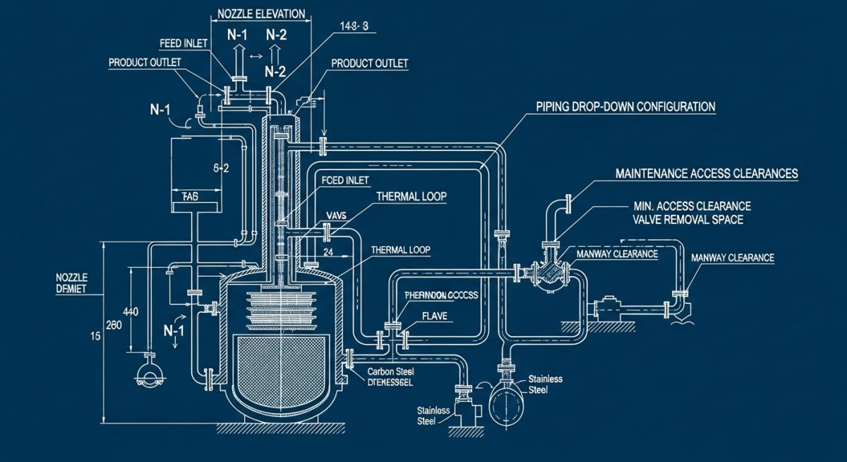
The orientation of nozzles is the foundation of successful tower design. For trayed columns, process nozzles must enter specific zones. For instance, feed nozzles must discharge into the downcomer or the active area of the tray depending on the process requirements. Manways must be positioned in the waste areas of the trays (where there are no downcomers) to allow maintenance personnel to enter and service the internals. I always establish a standardized coordinate system early, aligning the vessel’s 0-degree centerline with plant North to prevent orientation errors during fabrication.
Thermal Expansion and Stress Analysis Calculations
Thermal expansion is the single greatest structural challenge in vertical column design. Because the vessel shell and the vertical piping runs operate at different temperatures and are often made of different materials, they expand at different rates. This differential thermal expansion creates massive forces and moments at the vessel nozzles if not properly managed.
Let us look at a typical engineering calculation for vertical thermal expansion. Consider a fractionator column fabricated from carbon steel with a height of 40 meters, operating at a design temperature of 300 degrees Celsius. The ambient installation temperature is 20 degrees Celsius.
Thermal Expansion Calculation Parameters:
Vessel Material: Carbon Steel (ASTM A516 Gr. 70)
Coefficient of Thermal Expansion (alpha) at 300°C: 1.37e-5 mm/mm/°C
Vessel Height (L): 40,000 mm
Operating Temperature (T_op): 300°C
Ambient Temperature (T_amb): 20°C
Temperature Difference (dT): 300 – 20 = 280°C
Formula:
dL = L * alpha * dT
Calculation:
dL = 40,000 mm * 0.0000137 * 280
dL = 153.44 mm
A vertical expansion of over 153 mm is highly significant. If a rigid vertical pipe is anchored to the ground and connected to a nozzle at the top of this column, the resulting thermal thrust will easily rupture the nozzle or buckle the pipe. To mitigate this, we must design the vertical piping run with a “floating” support scheme.
The vertical line should be anchored near the vessel nozzle (using a rigid guide or anchor) so that the pipe and the nozzle move together. As the line runs down the column, it must be supported by guide supports attached to the vessel shell. These guides allow the pipe to slide vertically while restraining it laterally against wind and seismic forces. At the base of the column, where the line transitions to the horizontal sleepers or pipe rack, we must introduce a flexible expansion loop or offset to absorb the accumulated vertical expansion.
Never assume a vessel nozzle can support the weight of the connected piping. All vertical piping loads must be transferred back to the vessel shell via structural brackets or spring hangers. Nozzle loads must be rigorously verified using local stress analysis methods such as WRC 107, WRC 297, or finite element analysis (FEA) to ensure compliance with ASME Section VIII Division 1 limits.
Wind and Seismic Considerations
Tall towers act as vertical cantilevers. Under high wind velocities or seismic events, the top of the column will deflect laterally. The piping attached to the column must deflect with it. If the piping is supported rigidly from an external structure, the relative displacement between the swaying column and the rigid structure will cause catastrophic piping failures. Therefore, all piping guides and supports must be attached directly to the vessel shell, ensuring the piping moves in unison with the column.
Standard Clearances for Vertical Column Piping
[Piping Clearance Envelope]: The minimum physical spacing required between piping, structural steel, vessel shells, and insulation to ensure safe maintenance access and unhindered thermal movement.
To maintain a safe and maintainable plant layout, we must adhere to strict clearance envelopes. The table below outlines the minimum clearances that I enforce during the 3D model review stage of any major column design project.
| Parameter Description | Minimum Clearance | Engineering Rationale | Applicable Standard |
|---|---|---|---|
| Pipe to Vessel Shell (Bare to Bare) | 150 mm | Allows for insulation, paint maintenance, and shell inspection. | ASME B31.3 |
| Pipe Insulation to Platform Steel | 100 mm | Prevents clashing during thermal expansion and structural sway. | ASME B31.3 |
| Manway Clearance Radius | 1000 mm | Ensures davit arm swing and personnel egress during shutdowns. | OSHA 1910.146 |
| Platform Walkway Width | 750 mm | Provides safe passage for operators carrying tools and safety gear. | OSHA 1910.28 |
| Control Valve Handwheel Access | Operating Height | Must be within 1200 mm to 1500 mm above the platform floor. | ISA-RP60.1 |
The following matrix maps the primary piping systems associated with vertical columns, detailing their structural requirements, typical design parameters, and standard references.
| Piping System | Acronym | Primary Physical Parameters | Support Strategy | Reference Standard |
|---|---|---|---|---|
| Overhead Vapor Line | OVL | Large diameter (24″+), low pressure, high temperature. | Supported from top head nozzle; vertical run guided along shell. | ASME B31.3 / WRC 297 |
| Reboiler Liquid/Vapor | REB | Short, rigid runs, high thermal differential. | Rigidly supported; requires spring hangers if connected to kettle reboilers. | ASME Section VIII / B31.3 |
| Reflux Piping | RFL | Medium diameter (4″ to 8″), moderate temperature. | Guided along column shell; loop provided at bottom transition. | ASME B31.3 |
| Bottom Draw-off | BDO | High temperature, NPS 6″ to 12″, NPS 1.5″ drains. | Supported from concrete foundation; absorbs column downward expansion. | ASME B31.3 / API 610 |
Site Verification Checklist for Column Piping
[Field Verification Protocol]: A structured quality control process executed prior to hydrotesting to verify nozzle alignment, support clearances, and instrument accessibility against approved IFC drawings.
Before any vertical column piping system is released for hydrotesting and commissioning, a rigorous field walkdown must be performed. In my experience, minor deviations during the construction phase can lead to catastrophic failures during thermal startup. Use this checklist to verify the installation.
Pre-Commissioning Field Checklist
Verify that all process and instrument nozzles are oriented exactly as per the approved-for-construction (IFC) drawings. Check flange face parallelism and bolt hole alignment before torqueing.
Ensure all pipe guides have the specified clearance (typically 1.5 mm to 3 mm) to allow free vertical movement. Verify that spring hangers have their travel stops removed and are set to their cold load positions.
Confirm that all control valves, relief valves, and instruments (such as level glasses and transmitters) are fully accessible from the platforms. Check that ladder cages and safety gates comply with OSHA standards.
Verify that the top-head davit arm can swing freely without clashing with the overhead vapor line, platform handrails, or lighting poles. Test the swing path with a dummy load if possible.
Inspect the base expansion loops to ensure there are no temporary construction supports or debris blocking the calculated thermal expansion path.
Resolving Thermal Stress in Column Piping Design
[Thermal Stress Mitigation]: The engineering application of expansion loops, spring hangers, and directional guides to absorb differential thermal expansion between a hot process vessel and its associated piping.
Field Case Study: Real-World Application
During the commissioning phase of a 45-meter-tall vacuum fractionator operating at 340 degrees Celsius, field operators reported visible deformation on the 24-inch overhead vapor nozzle. The piping stress analysis had been performed using simplified assumptions, treating the column as a rigid anchor. In reality, the differential thermal expansion between the carbon steel vessel shell and the stainless steel overhead line was not fully absorbed. The rigid guide supports near the top of the column locked up, transferring a massive bending moment of 180,000 N-m directly to the nozzle neck, exceeding the allowable limits of ASME B31.3 by over 200%.
I was brought in to lead the recovery effort. We immediately modeled the entire system in CAESAR II, incorporating the exact thermal growth profile of the vessel shell. We implemented a three-part engineering solution:
- We replaced the rigid guide supports on the upper 15 meters of the column with spring-loaded guide assemblies to allow controlled vertical movement.
- We redesigned the base of the vertical run, adding a 6-meter horizontal expansion loop with low-friction PTFE slide plates to absorb the 172 mm of downward thermal growth.
- We reinforced the overhead nozzle with a custom-engineered reinforcing pad designed in accordance with ASME Section VIII Division 1.
These modifications reduced the nozzle bending moment to a safe 35,000 N-m, well within code compliance. The column has now been operating safely for over five years without a single incident.
My direct recommendation for all tall tower projects is to perform a comprehensive, coupled stress analysis that models both the vessel shell thermal growth and the piping system simultaneously. Never rely on simplified hand calculations for lines larger than 8 inches operating above 200 degrees Celsius.
Frequently Asked Engineering Questions
1. How do you determine the location of the first guide support on a vertical column?
2. Why is a drop-out spool required for reboiler piping systems?
3. How does wind load affect the design of vertical piping guides?
4. What is the purpose of a utility piping station on a column platform?
5. How do you manage the piping layout around a column manway?
6. When should spring hangers be used instead of rigid guides on a column?
===FAQ_BLOCK===
Complete Course on
Piping Engineering
Check Now
Key Features
- 125+ Hours Content
- 500+ Recorded Lectures
- 20+ Years Exp.
- Lifetime Access
Coverage
- Codes & Standards
- Layouts & Design
- Material Eng.
- Stress Analysis



