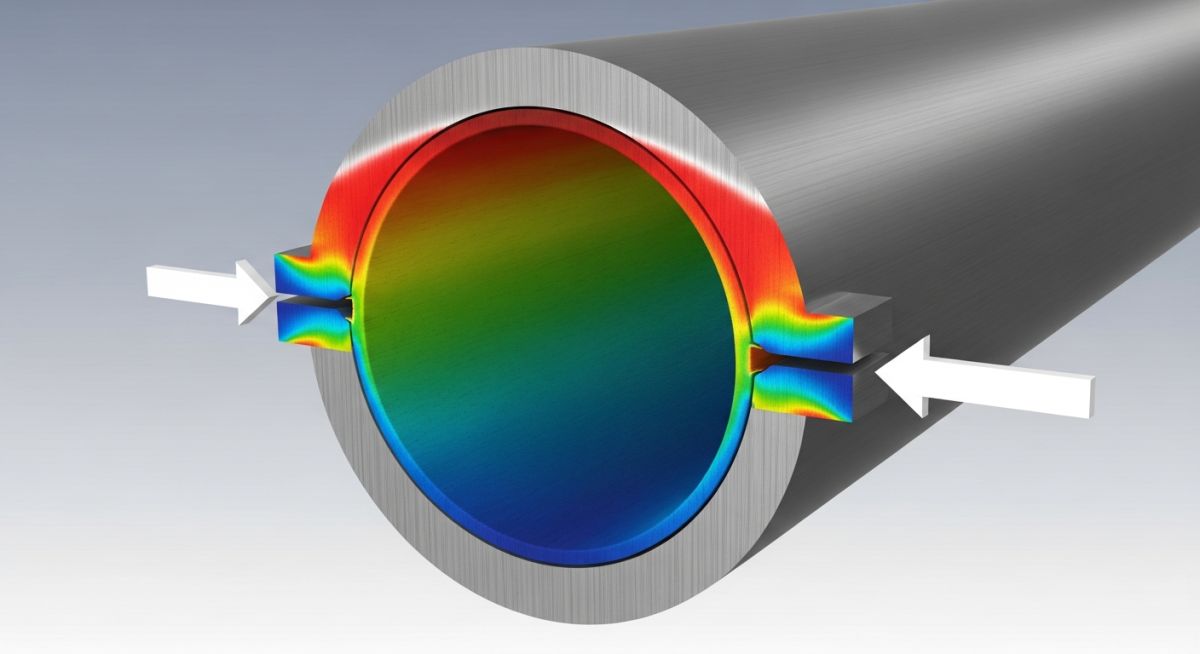
Structural Design Trade-offs: The engineering balance between maximizing system flexibility to reduce stress and maintaining sufficient rigidity to prevent excessive vibration or sagging under operational loads.
Advantages of High Flexibility
- Reduces nozzle loads on sensitive rotating equipment.
- Extends fatigue life by keeping stress ranges below endurance limits.
- Minimizes the need for complex expansion joints.
- Allows for easier installation and field fit-up adjustments.
Disadvantages of High Flexibility
- Increases susceptibility to flow-induced vibration (FIV).
- Requires more frequent support structures, increasing capital costs.
- May lead to excessive sagging if not properly supported.
- Increases the complexity of the stress analysis model.
Engineering Implementation: The practical application of stress and strain principles across diverse industrial sectors to ensure structural integrity under extreme thermal and pressure conditions.
High-Temperature Steam Headers
In power generation, steam headers operate at extreme temperatures where thermal expansion is the primary design driver. Engineers must design loops and offsets to absorb the massive strain, ensuring that the resulting stress at the branch connections remains within the allowable limits defined by ASME B31.1.
Cryogenic Liquefied Gas Transfer
Cryogenic systems face the opposite challenge, where extreme cold causes significant contraction. The strain induced by this contraction can lead to brittle fracture if the material selection and flexibility are not perfectly matched to the thermal cycle.
Refinery Process Piping Networks
Refinery piping often involves complex routing through congested pipe racks. Managing the interaction between thermal strain and existing support structures is vital to prevent localized stress concentrations that could lead to leaks in hazardous service lines.
In my two decades of piping stress analysis, I have observed that engineers often conflate the sequence of mechanical response. When evaluating piping systems under thermal expansion, we must distinguish between the independent variable (strain) and the dependent variable (stress). The following table outlines the critical material properties and their relationship to the ASME B31.3 code requirements for allowable stress ranges.
Understanding these parameters is vital for accurate flexibility analysis. The table below provides a reference for how material modulus and thermal expansion coefficients dictate the resulting stress state when the pipe is constrained by anchors or equipment nozzles.
| Parameter | Symbol | Physical Significance | Code Reference |
|---|---|---|---|
| Youngs Modulus | E | Stiffness of material relating stress to strain | ASME B31.3 Table C-1 |
| Thermal Expansion | alpha | Strain induced per unit temperature change | ASME B31.3 Table C-1 |
| Allowable Stress | Sa | Maximum permitted stress range for fatigue | ASME B31.3 Para 302.3.5 |
By utilizing these constants, we can calculate the displacement-induced stress. Always ensure that the modulus of elasticity is adjusted for the operating temperature, as specified in the code, to avoid underestimating the reaction forces at the equipment interface.
The interaction between mechanical loads and material response requires a structured approach to data management. This matrix maps the physical entities involved in stress analysis to their respective governing standards and mathematical definitions, ensuring that every calculation remains traceable to industry-recognized benchmarks.
Engineers must maintain this mapping to ensure that software inputs for pipe stress analysis—such as Caesar II or AutoPIPE—align with the physical reality of the piping system. Discrepancies in these mappings often lead to non-conservative design outcomes.
| Entity | Acronym | Standard | Primary Function |
|---|---|---|---|
| Stress Intensification Factor | SIF | ASME B31.3 | Fatigue life reduction at fittings |
| Flexibility Characteristic | h | ASME B31.3 | Geometry-based flexibility factor |
| Poisson Ratio | nu | ASTM E132 | Lateral strain vs axial strain |
This matrix serves as a foundational guide for junior engineers. When performing a stress analysis, verify that the SIF values are correctly applied to all branch connections and elbows, as these are the primary locations where strain energy is converted into localized stress concentrations.
Verification of piping systems requires a systematic approach to ensure that the theoretical model matches the physical installation. In my experience, the most common failures occur when the field installation deviates from the stress analysis model regarding support placement or thermal expansion gaps. Use this checklist to validate your design against site conditions.
-
1.
Verify that all spring hangers are set to the calculated cold load position as per the stress report. -
2.
Confirm that expansion joints are not over-extended during installation, which would induce unintended initial strain. -
3.
Check that all rigid anchors are installed at the exact coordinates specified in the isometric drawings. -
4.
Inspect for any “cold spring” requirements; ensure the gap is measured accurately before final welding. -
5.
Validate that no temporary construction supports remain, as these create artificial constraints that alter the stress distribution.
Regular site audits are mandatory for high-temperature systems. If you find that the pipe is touching a structural member that was not modeled, you must re-run the analysis. The presence of an unmodeled contact point changes the boundary conditions, effectively turning a flexible system into a rigid one, which can lead to premature fatigue failure at the nozzle connections.
Problem: Excessive Nozzle Loading at High-Temperature Pump
- Thermal expansion caused the suction nozzle to deflect beyond the manufacturer’s allowable limit.
- The stress analysis model failed to account for the actual stiffness of the pump casing.
- Field measurements showed a 15mm displacement that was not predicted in the initial design phase.
- The piping system was constrained by a rigid support located too close to the pump nozzle.
Outcome: Successful Mitigation via Flexibility Optimization
- Relocated the primary support to increase the flexibility of the piping leg.
- Implemented a cold-springing technique to offset the thermal expansion displacement.
- Reduced the nozzle reaction forces by 40 percent, bringing them within the API 610 limits.
- Verified the new configuration with a secondary stress analysis run to ensure code compliance.
My recommendation for similar cases is to always perform a sensitivity analysis on support stiffness. Often, the difference between a passing and failing design is the assumption of support rigidity. By modeling the actual stiffness of the steel structure, you can achieve a more realistic stress distribution and avoid unnecessary field modifications.
Frequently Asked Engineering Questions
Does strain always lead to stress in piping?
- In an unconstrained pipe, thermal expansion causes strain but zero stress.
- When you introduce an anchor, you prevent the strain, which forces the material to develop internal stress.
- ASME B31.3 focuses on the stress range resulting from these constraints.
How does ASME B31.3 define the stress range?
- It accounts for the fatigue life of the piping system.
- The allowable stress range is calculated using the formula involving the basic allowable stress at ambient and operating temperatures.
- This approach ensures that the pipe can withstand the cyclic nature of thermal expansion.
What is the role of Youngs Modulus in analysis?
- It determines the stiffness of the piping system.
- Higher modulus values result in higher reaction forces for the same amount of thermal displacement.
- Engineers must use the temperature-dependent modulus values provided in ASME B31.3 to maintain accuracy.
Why is SIF important for stress calculations?
- It is a multiplier used to estimate the fatigue life reduction.
- Without SIF, the calculated stress would be non-conservative and dangerous.
- ASME B31.3 provides empirical formulas to determine these factors based on pipe geometry.
How do I handle cold spring in design?
- It involves cutting the pipe shorter than the required length to force a displacement during installation.
- The code allows for a credit in the stress range calculation if the cold spring is properly documented.
- It is a useful technique for reducing nozzle loads on sensitive rotating equipment.
Can thermal strain cause plastic deformation?
- This is known as self-springing or shakedown in piping systems.
- While the code generally assumes elastic behavior, localized yielding is often acceptable if it leads to a stable state.
- However, excessive plastic deformation can lead to low-cycle fatigue failure over time.
Complete Course on
Piping Engineering
Check Now
Key Features
- 125+ Hours Content
- 500+ Recorded Lectures
- 20+ Years Exp.
- Lifetime Access
Coverage
- Codes & Standards
- Layouts & Design
- Material Eng.
- Stress Analysis
