Understanding Shear Modulus and Modulus of Rigidity in Piping Design
In my 20 years of piping engineering, I have seen many young engineers focus almost exclusively on Young’s Modulus when setting up stress analyses. However, when you are dealing with complex 3D piping manifolds, thermal expansion loops, or reciprocating compressor discharge lines, the modulus of rigidity—commonly known as the shear modulus—becomes the true gatekeeper of structural integrity. If you miscalculate how a pipe twists under torsional loads, you risk localized buckling, flange leakage, and catastrophic support failures.
This guide draws directly from my field experience and the strict mandates of ASME B31.3. We will break down the mathematical relationships, analyze temperature-dependent material behaviors, and look at how these values are implemented in modern stress analysis software like CAESAR II.
Key Takeaways
- Understand the direct mathematical link between Young’s Modulus, Poisson’s Ratio, and Shear Modulus.
- Identify how elevated operating temperatures degrade the modulus of rigidity in process piping.
- Learn to extract and verify correct elastic constants from ASME Section II Part D.
- Discover how torsional stress limits prevent fatigue failures in rotating equipment connections.
How Does Shear Modulus Impact Piping Stress Analysis?
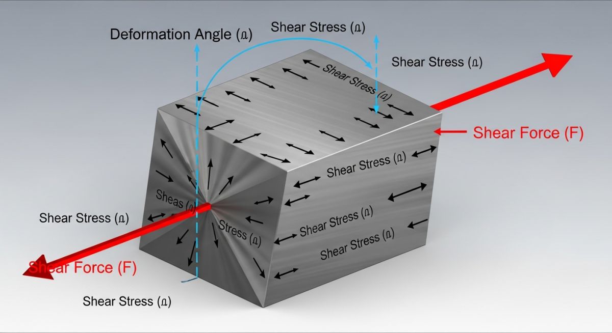
Shear Modulus: The ratio of shear stress to shear strain within the elastic limit of a material, serving as a key parameter for calculating torsional deflection and structural rigidity. It governs how piping systems absorb rotational forces without experiencing permanent plastic deformation.
To understand this physically, imagine a pipe subjected to a twisting moment (torque). Unlike axial tension which stretches the material fibers, or bending which curves them, torsion slides parallel planes of the material relative to one another. The shear modulus, denoted by the symbol G, represents the stiffness of the material against this sliding action.
The Governing Mathematical Equations
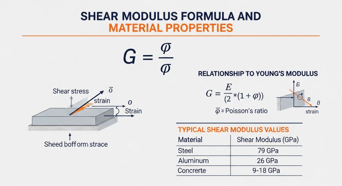
The fundamental definition of the shear modulus is expressed as:
Where:
- G = Shear Modulus (typically expressed in GPa or psi)
- tau (τ) = Shear Stress (Force divided by the shearing area, F / A)
- gamma (γ) = Shear Strain (angular deformation in radians, dx / L)
For isotropic materials—materials that exhibit identical physical properties in all directions—the shear modulus is directly coupled to Young’s Modulus (E) and Poisson’s Ratio (nu or ν) through the following elastic relationship:
This relationship is highly significant. It means that if you know any two of these elastic constants, you can mathematically derive the third. For instance, a typical carbon steel at room temperature has a Young’s Modulus of approximately 200 GPa and a Poisson’s Ratio of 0.30. Plugging these values into our equation yields a shear modulus of roughly 76.9 GPa.
In high-temperature process environments, both Young’s Modulus and Shear Modulus degrade significantly. Using ambient-temperature elastic constants for a system operating at 400°C (750°F) will lead to an overestimation of system stiffness. This error results in calculated thermal expansion forces that are artificially high, leading to over-designed, expensive support structures, or worse, underestimated actual displacements that cause field failures. Always reference ASME Section II Part D Table TM-1 and Table TM-4 for temperature-corrected values.
Torsional Rigidity in Pipe Geometries
When we translate this material property into structural piping design, we look at torsional rigidity. The torsional stiffness of a circular pipe is a function of its shear modulus and its polar moment of inertia (J). The angle of twist (theta) for a pipe of length L under torque T is calculated as:
For a hollow pipe with outer diameter Do and inner diameter Di, the polar moment of inertia is:
If your software uses an incorrect value for G, your calculated rotational deflections at equipment nozzles will be incorrect. This is especially dangerous when connecting to strain-sensitive machinery like centrifugal pumps or steam turbines governed by API 610 and API 617 limits.
Why Is Shear Modulus Critical for Material Selection?
Material Rigidity: The physical capacity of an alloy to resist angular distortion under external torsional loads. This property dictates the spacing of structural supports and the flexibility of piping loops under thermal expansion.
Different alloys exhibit vastly different elastic behaviors. When designing systems that experience high dynamic loads or thermal cycles, selecting a material with an appropriate shear modulus is essential. Below is a reference table detailing common piping materials, their elastic constants at ambient temperature (20°C / 70°F), and their corresponding ASME specifications.
| Material Description | ASME Spec | Young’s Modulus E (GPa) | Poisson’s Ratio (nu) | Shear Modulus G (GPa) |
|---|---|---|---|---|
| Carbon Steel | ASTM A106 Gr. B | 203.0 | 0.30 | 78.0 |
| Stainless Steel 304 | ASTM A312 TP304 | 193.0 | 0.29 | 74.8 |
| Chrome-Moly Steel | ASTM A335 Gr. P11 | 205.0 | 0.30 | 78.8 |
| Titanium Gr. 2 | ASTM B338 Gr. 2 | 105.0 | 0.34 | 39.2 |
| Aluminum 6061-T6 | ASTM B209 | 68.9 | 0.33 | 25.9 |
To ensure seamless integration between material science and structural design, engineers must map physical parameters to industry codes. The matrix below outlines how shear modulus interacts with design codes and stress analysis software.
| Design Parameter | Primary Code Reference | Software Input Field | Impact on System Analysis |
|---|---|---|---|
| Torsional Stress Limits | ASME B31.3 Chapter II | Code Stress / Allowable Stress | Determines the maximum safe twisting moment on straight runs and fittings. |
| Temperature Derating | ASME Sec II Part D Table TM-4 | Temperature-Dependent G | Adjusts system flexibility calculations based on actual operating temperature. |
| Dynamic Modal Analysis | ASME B31.3 Appendix F | Mass & Stiffness Matrices | Directly influences natural frequencies and torsional vibration modes. |
| Flange Leakage Evaluation | ASME Section VIII Div 1 / NC-3658 | External Moment Loading | Calculates how torsional shear forces translate into gasket unloading. |
How to Verify Shear Modulus on Site?
Field Verification: The process of confirming material elastic properties using non-destructive testing methods like ultrasonic velocity measurements. This ensures that the installed piping matches the design assumptions of the stress analysis software.
During construction and commissioning, material mix-ups can occur. If a low-rigidity alloy is mistakenly installed in place of a high-rigidity carbon steel, the entire piping system’s support scheme could fail. I use this checklist on-site to verify material properties and ensure compliance with design specifications.
Piping Material Rigidity Verification Checklist
-
Positive Material Identification (PMI): Perform PMI testing on all critical alloy piping runs to verify chemical composition matches the design spec (e.g., ASTM A335 P11 or P22).
-
Ultrasonic Thickness & Velocity Testing: Measure shear wave and longitudinal wave velocities. The ratio of these velocities directly yields the dynamic Poisson’s ratio and shear modulus of the in-situ material.
-
Mill Test Certificate (MTC) Audit: Cross-reference the heat numbers stamped on the pipes with the MTCs to confirm that the elastic modulus and chemical properties comply with ASME Section II.
-
Stress Analysis Software Input Audit: Verify that the stress analyst did not use the default room-temperature shear modulus (G) for lines operating above 150°C (300°F).
-
Support Alignment and Clearance Check: Inspect torsional guides and anchors to ensure they allow for calculated angular rotations without binding or causing localized pipe wall deformation.
Field Case Study: Real-World Application
The Problem: Vibration-Induced Fatigue and Support Failure
At a natural gas compressor station in Alberta, a 12-inch ASTM A106 Gr. B discharge line operating at 280°C (536°F) experienced severe, high-amplitude vibrations. Within three months of commissioning, a heavy-duty structural guide support sheared off at the anchor bolts.
Our investigation revealed that the original stress analyst had used the default ambient-temperature shear modulus of 78.0 GPa in the CAESAR II model, instead of derating it to 71.2 GPa as required for 280°C by ASME Section II Part D. This error caused the software to underestimate the system’s torsional flexibility, leading to an incorrect support configuration that over-constrained the pipe and concentrated dynamic torsional forces directly onto the support bracket.
The Outcome: Corrective Engineering and System Stabilization
I led the remediation team. We updated the stress model with the correct temperature-derated shear modulus of 71.2 GPa. The revised analysis showed that the pipe was actually much more flexible in torsion than originally calculated, which shifted the natural frequency of the piping loop directly into the operating frequency range of the reciprocating compressor.
To resolve this, we redesigned the support scheme. We replaced the rigid guide with a tuned spring hanger and added a viscoelastic damper. This modified setup shifted the system’s natural frequency away from the excitation frequency, reducing torsional stress by 42% and completely eliminating the vibration-induced fatigue risk.
This project highlights a critical lesson: material properties are not static. Always design for your maximum operating temperature, and never assume software defaults are correct without manual verification against the governing codes.
Frequently Asked Engineering Questions
What is the difference between Young’s Modulus and Shear Modulus?
How does temperature affect the Modulus of Rigidity?
Can I calculate Shear Modulus if I only know Young’s Modulus?
Why is Shear Modulus important for rotating equipment connections?
What are the typical units for Shear Modulus in engineering?
How does CAESAR II utilize the Shear Modulus?
===
Complete Course on
Piping Engineering
Check Now
Key Features
- 125+ Hours Content
- 500+ Recorded Lectures
- 20+ Years Exp.
- Lifetime Access
Coverage
- Codes & Standards
- Layouts & Design
- Material Eng.
- Stress Analysis
