Table of Contents

How to Select and Design Pipe Hanger Supports for Industrial Piping
In my 20 plus years of field experience, I have seen many piping systems fail not because of poor pipe wall thickness calculations, but due to poorly selected pipe hanger supports. When you are dealing with high-temperature steam lines or heavy process fluids, how you suspend those lines determines the structural integrity of the entire plant. A hanger that is too rigid can restrict thermal expansion, leading to massive flange leaks or nozzle overloads at connected pumps and turbines.
I remember a project in a petrochemical facility where a 12-inch steam line kept tearing its structural attachments. The original designer had specified simple rigid rod hangers where a variable spring hanger was required to handle the thermal growth. Once we calculated the actual thermal travel and replaced the rigid rods with properly calibrated spring hangers, the system settled into a smooth, reliable operating cycle.
Key Engineering Takeaways
- Understand the clear distinction between rigid, variable, and constant support hangers.
- Learn how to calculate hanger load distributions and spring variability limits.
- Identify the exact code requirements under ASME B31.3 and MSS SP-58.
- Avoid common field installation errors that lead to spring binding and structural failure.
Complete Course on
Piping Engineering
Check Now
Key Features
- 125+ Hours Content
- 500+ Recorded Lectures
- 20+ Years Exp.
- Lifetime Access
Coverage
- Codes & Standards
- Layouts & Design
- Material Eng.
- Stress Analysis
How to Select Pipe Hanger Supports Properly
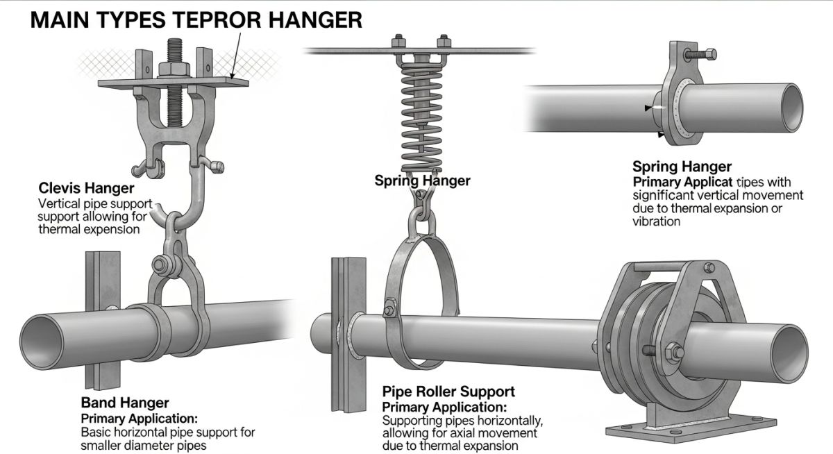
When designing a piping system, we classify hangers into three primary categories based on their mechanical behavior: rigid hangers, variable spring hangers, and constant spring hangers. Selecting the wrong type can introduce destructive stresses into your piping network.
1. Rigid Hanger Supports
Rigid hangers are the simplest and most cost-effective option. They prevent vertical movement completely while allowing limited lateral swing via a threaded rod and clevis assembly. I specify rigid hangers only when vertical thermal movement is negligible (typically less than 2 millimeters). If you install a rigid hanger on a line with significant upward thermal expansion, the pipe will lift off the support, transferring its entire deadweight to adjacent supports or equipment nozzles.
2. Variable Spring Hangers
Variable spring hangers utilize a pre-compressed helical coil spring to support the pipe weight. As the pipe expands vertically, the spring compresses or extends, meaning the supporting force varies throughout the thermal cycle.
To design these safely, we must calculate the spring variability. According to ASME B31.3 and MSS SP-58, the variability should not exceed 25 percent for standard applications. The formula to determine variability is:
Let us look at a practical calculation. Suppose we have an operating load (hot load) of 12,000 Newtons, and the thermal travel is 15 millimeters upward. If we select a spring with a spring rate of 120 Newtons per millimeter:
- Change in Load = 15 mm * 120 N/mm = 1,800 Newtons
- Cold Load (Pre-load) = 12,000 N + 1,800 N = 13,800 Newtons
- Variability = (1,800 N / 12,000 N) * 100 = 15 percent
Since 15 percent is well below the 25 percent limit, this variable spring selection is acceptable for the design.
3. Constant Spring Hangers
When thermal travel is large (typically exceeding 50 millimeters) or when the allowable load variation on sensitive equipment nozzles is extremely tight, variable springs are no longer suitable. In these scenarios, I always specify constant spring hangers. These devices use a counterbalancing mechanical linkage to maintain a virtually constant supporting force throughout the entire travel range, keeping load variation under 5 percent.
Standard Load Ratings for Hanger Components
To ensure structural safety, all hanger components must be sized based on the maximum operating weight of the piping system, including the weight of the fluid, insulation, and any hydrostatic testing loads. The table below outlines the maximum recommended loads for carbon steel threaded hanger rods at elevated temperatures according to MSS SP-58.
| Rod Diameter (Inches) | Max Load at 650°F / 343°C (lbs) | Max Load at 650°F / 343°C (kg) | Thread Pitch (UNC) |
|---|---|---|---|
| 3/8 | 610 | 277 | 16 |
| 1/2 | 1,130 | 513 | 13 |
| 5/8 | 1,810 | 821 | 11 |
| 3/4 | 2,710 | 1,229 | 10 |
| 7/8 | 3,770 | 1,710 | 9 |
| 1 | 4,960 | 2,250 | 8 |
Technical Mapping & Specifications Matrix
The following matrix maps the primary types of pipe hanger supports to their specific industrial applications, design standards, and mechanical limitations.
| Hanger Type | Primary Function | Typical Application | Standard Reference |
|---|---|---|---|
| Rigid Rod Hanger | Pure vertical support with zero upward thermal movement. | Cold water lines, utility piping, ambient process lines. | MSS SP-58 Type 1 |
| Variable Spring | Supports weight while permitting moderate vertical travel. | Medium-temperature steam, hydrocarbon process lines. | MSS SP-58 Type 51 / 52 |
| Constant Spring | Provides constant supporting force through large travel. | High-pressure steam, boiler feed water, turbine connections. | MSS SP-58 Type 54 / 55 |
| Sway Brace | Opposes dynamic forces, vibration, and wind loads. | Compressor discharge lines, seismic-prone areas. | MSS SP-58 Type 50 |
Field Inspection of Pipe Hanger Supports
During plant commissioning, I have walked down thousands of meters of piping. It is incredibly common to find spring hangers with their travel stops still installed, or rods bent because the pipe moved further than the designer anticipated. Use this field checklist to verify your installations before starting up any process system.
Pre-Commissioning Hanger Checklist
Ensure all factory-installed travel stops (locking pins or plates) are completely removed from spring hangers before hydrostatic testing or hot startup.
Verify that the spring pointer aligns exactly with the “C” (Cold) mark on the scale plate when the system is cold and filled with process fluid.
Check that the hanger rod angle does not exceed 4 degrees from vertical in the hot operating condition to prevent bending stresses on the rod.
Confirm that all threaded connections, turnbuckles, and rod couplings have full thread engagement and are locked tightly with locknuts.
Inspect the welds or beam clamps connecting the hanger to the structural steel. Look for signs of deformation, cracking, or paint peeling.
Field Case Study: Real-World Application
The Problem: Repeated Flange Leaks on a High-Pressure Steam Header
At a combined-cycle power plant, a 16-inch main steam line operating at 540°C (1004°F) experienced chronic flange leaks at the turbine stop valve connection. The plant operator had replaced the gaskets three times within a single year, but the leaks returned after every thermal cycle.
Upon field inspection, I discovered that the piping designer had installed rigid rod hangers near the turbine connection. As the steam line heated up, it expanded upward by 38 millimeters. Because the rigid hangers could not yield, they acted as a fulcrum, transferring a massive bending moment directly to the turbine flange, exceeding the allowable limits of ASME B31.1.
The Outcome: Redesigning with Constant Spring Hangers
We performed a comprehensive pipe stress analysis using CAESAR II software. The simulation showed that replacing the first three rigid hangers with constant spring hangers would reduce the bending moment on the turbine nozzle by 85 percent.
We selected constant spring hangers with a load capacity of 4,200 kilograms and a travel range of 50 millimeters. After installation and removal of the travel stops, the steam line expanded smoothly without lifting off its supports. The plant has now run for over three years without a single flange leak at the turbine interface.
My direct recommendation for any high-temperature system is to always model the piping system in stress analysis software before finalizing support locations. Never guess when it comes to thermal expansion and nozzle load limits.
Frequently Asked Engineering Questions
What is the difference between a variable spring hanger and a constant spring hanger?
Why is spring variability limited to 25 percent in piping design?
What happens if you forget to remove the travel stops from a spring hanger?
How do you determine the spacing between pipe hanger supports?
Can threaded hanger rods be welded to structural steel?
What is the purpose of a sway brace in a piping system?

📚 Recommended Resources: pipe hanger supports
Read these Guides
🎓 Advanced Training


Related posts:
![A mechanical sucker rod pumpjack operating in an oil field at sunset]()
What is Sucker Rod Pump System in Oil Production?
![Piping material engineer reviewing technical specifications on a tablet in an industrial plant.]()
How a Piping Material Engineer Drives Industrial Project Success
![Industrial refinery plant showing various types of static equipment]()
What is Static Equipment? Types and List of Static Equipments
![Side-by-side comparison of industrial process piping and power plant steam piping systems.]()
Differences Between ASME B31.3 and B31.1: B31.3 vs B31.1
![Large industrial steel storage tank under construction with cranes and scaffolding]()
Storage Tank Construction Method Statement: Step-by-Step Engineering Guide
![Cutaway diagram of a globe control valve highlighting the internal valve trim components]()
What is a Valve Trim? Types, Components, and Selection


