What is a Trapeze Hanger and How Does It Support Heavy Piping?
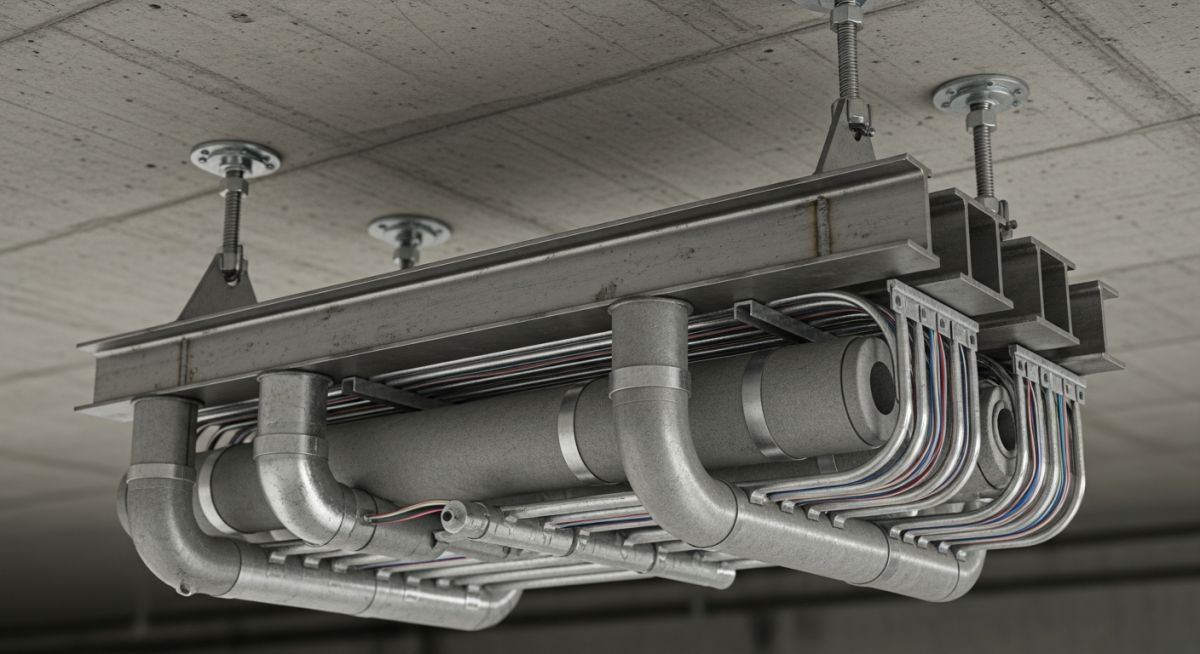
In my 20 plus years of designing piping systems for refineries, chemical plants, and large-scale commercial facilities, I have seen engineers struggle repeatedly with congested overhead spaces. Routing individual pipe hangers for ten parallel lines is not only a spatial nightmare, but it also drives up structural fabrication costs. This is where the utility of a robust trapeze hanger becomes apparent. By consolidating multiple lines onto a single horizontal member, we save valuable overhead space, reduce structural anchor points, and simplify the installation process.
Throughout my career, I have relied on these versatile supports to handle everything from lightweight electrical conduits to heavy, high-pressure process lines. However, designing them requires a deep understanding of structural mechanics, load distribution, and code compliance. If you do not calculate the bending moments or account for thermal expansion, you risk structural failure that can compromise the entire piping run.
- Consolidates multiple parallel lines onto a single structural support to optimize overhead space.
- Requires rigorous calculation of bending moments, shear forces, and rod tension under full operating loads.
- Must comply with industry standards such as MSS SP-58, ASME B31.1, and ASME B31.3.
- Demands careful consideration of thermal expansion to prevent torsional stress on the strut channel.
Complete Course on
Piping Engineering
Check Now
Key Features
- 125+ Hours Content
- 500+ Recorded Lectures
- 20+ Years Exp.
- Lifetime Access
Coverage
- Codes & Standards
- Layouts & Design
- Material Eng.
- Stress Analysis
How to Design a Trapeze Hanger System
When I sit down to design a trapeze support, the first step is always identifying the physical properties of the lines being supported. We must account for the weight of the pipe, the fluid inside, the insulation, and any potential dynamic loads such as water hammer or wind if the system is semi-exposed.
Step-by-Step Structural Calculations
Let us walk through a real-world design scenario. Imagine we have a trapeze hanger supporting three parallel process lines. The span of our horizontal strut channel (L) is 48 inches. The three concentrated loads (P1, P2, and P3) are spaced evenly across the span, each exerting a downward force of 200 pounds.
Since the loading is perfectly symmetrical:
R1 = R2 = (P1 + P2 + P3) / 2
R1 = R2 = (200 + 200 + 200) / 2 = 300 lbs
2. Determine Maximum Bending Moment (M):
The loads are located at 12 inches, 24 inches, and 36 inches from the left support.
Bending Moment at 12 inches:
M = R1 * 12 = 300 * 12 = 3600 in-lbs
Bending Moment at 24 inches (center):
M = (R1 * 24) – (P1 * 12) = (300 * 24) – (200 * 12) = 7200 – 2400 = 4800 in-lbs
Therefore, the Maximum Bending Moment (M_max) is 4800 in-lbs.
3. Select Strut Channel and Verify Bending Stress (f):
Let us select a standard 12-gauge steel strut channel (1-5/8″ x 1-5/8″) with a section modulus (S) of 0.203 in³.
f = M_max / S
f = 4800 / 0.203 = 23,645 psi
Compare this with the allowable bending stress of ASTM A1011 Grade 33 steel (typically 25,000 psi). The design is safe but has a narrow margin.
In my experience, if your calculated bending stress is within 10% of the allowable limit, it is wise to step up to a deeper channel (such as 1-5/8″ x 3-1/4″) or use a back-to-back double channel configuration. This provides an extra safety margin for unexpected process upsets or future line additions.
Never rigidly clamp multiple lines with different operating temperatures to the same trapeze hanger. If one line operates at 300°F and the adjacent line is cold, the thermal expansion of the hot line will exert massive axial forces. This can twist the strut channel, bend the hanger rods, and cause catastrophic structural failure. Always use slide plates, Teflon guides, or roller supports for hot lines.
Code Compliance and Standards
All professional piping designs must align with recognized codes. For industrial process piping, ASME B31.3 governs the overall system design, while MSS SP-58 provides the specific material, design, and fabrication requirements for pipe hangers and supports. Adhering to these standards ensures that your hanger rods are sized correctly for tensile strength and that your structural attachments can handle the design loads without yielding.
What Are Trapeze Hanger Load Ratings?
To simplify the design process, I often refer to standardized load tables. Below is a reference table for a standard 1-5/8″ x 1-5/8″ 12-Gauge Steel Strut Channel, showing how the allowable uniform load and concentrated center load decrease as the span increases.
| Span (Inches) | Max Allowable Uniform Load (lbs) | Deflection at Max Uniform Load (in) | Max Concentrated Center Load (lbs) |
|---|---|---|---|
| 18 | 1,500 | 0.02 | 750 |
| 24 | 1,130 | 0.04 | 565 |
| 36 | 750 | 0.09 | 375 |
| 48 | 560 | 0.16 | 280 |
| 60 | 450 | 0.25 | 225 |
In addition to the horizontal strut, we must size the vertical hanger rods. The table below outlines the safe load limits for carbon steel threaded rods (ASTM A36 / A307) at typical operating temperatures up to 650°F, in accordance with MSS SP-58.
| Rod Diameter (Inches) | Root Area of Thread (sq in) | Max Safe Load at 650°F (lbs) | Recommended Installation Torque (ft-lbs) |
|---|---|---|---|
| 3/8 | 0.068 | 730 | 15 |
| 1/2 | 0.126 | 1,350 | 30 |
| 5/8 | 0.202 | 2,160 | 60 |
| 3/4 | 0.302 | 3,230 | 100 |
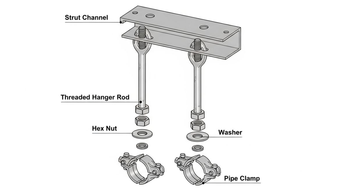
To ensure seamless procurement and engineering alignment, this matrix maps the core components of a trapeze assembly to their respective material standards and primary functions.
| Component | Standard Reference | Primary Function | Common Material Spec |
|---|---|---|---|
| Strut Channel | MFMA-4 | Horizontal load-bearing beam | ASTM A1011 Carbon Steel / Hot-Dip Galv |
| Hanger Rods | ASTM F1554 / A307 | Vertical tension suspension | ASTM A36 Carbon Steel / Zinc Plated |
| Pipe Clamps | MSS SP-58 Type 1, 8 | Securing pipe to strut channel | ASTM A1011 or Electro-Galvanized Steel |
| Beam Clamps | MSS SP-58 Type 19, 21 | Anchoring rods to structural steel | Malleable Iron / ASTM A197 |
When to Use a Trapeze Hanger Support
During my field audits, I frequently encounter poorly installed trapeze supports. A common mistake is assuming that because the design was done in an office, the field installation will automatically be perfect. I always insist on a rigorous field inspection using a structured checklist before any piping system is hydrotested or put into service.
-
Rod Verticality: Verify that the vertical hanger rods are plumb within 4 degrees of vertical. Out-of-plumb rods introduce unwanted bending stresses into the rods and structural anchors.
-
Thread Engagement: Ensure that the hanger rods have full thread engagement in both the upper beam clamp and the lower channel nuts. A minimum engagement equal to the rod diameter is required.
-
Locknut Installation: Confirm that locknuts are installed and tightened at all connection points to prevent loosening due to system vibration.
-
Strut Levelness: Check that the horizontal strut channel is level across its span. An unlevel channel causes uneven load distribution, overloading one hanger rod.
-
Thermal Movement Clearance: Verify that pipes requiring thermal expansion have adequate clearance to slide on the strut without binding or hitting adjacent lines.
Field Case Study: Real-World Application
During the construction of a combined-cycle power plant in Texas, the basement of the turbine building was severely congested. The original design called for 12 independent pipe hangers to support a series of parallel cooling water and condensate lines. The individual hangers clashed with electrical cable trays, and the overhead concrete deck was becoming overcrowded with anchor bolts, risking structural micro-cracking.
I stepped in and redesigned the entire run using a series of heavy-duty, multi-tier trapeze hangers. By consolidating the 12 lines onto 4 double-tier trapeze assemblies, we reduced the number of concrete anchor points by 66%. We utilized heavy-duty structural steel channels (C3x4.1) instead of light-gauge strut to handle the combined static weight of 3,200 lbs per bay.
The results were immediate. The installation labor costs dropped by 40%, and we completely eliminated the spatial clashes with the electrical trays. Most importantly, the structural integrity of the concrete deck was preserved by reducing the density of anchor bolts. This project proved once again that a well-engineered trapeze system is far superior to individual hangers in congested industrial environments.
Frequently Asked Engineering Questions
What is the maximum spacing allowed between trapeze hangers?
Can you mix hot and cold piping on the same trapeze hanger?
How do you calculate the required rod size for a trapeze hanger?
What materials are typically used for trapeze hangers?
How do you prevent galvanic corrosion on a trapeze hanger?
What is the difference between a pipe hanger and a trapeze hanger?
===FAQ_BLOCK===

Related posts:
![Aerial view of a BESS facility construction site showing earthwork grading, soil compaction, and site preparation for battery storage containers.]()
Earthwork Optimization for BESS Facilities: A Civil Engineering Guide
![Isometric view of a BESS site grading design showing battery containers, access roads, and perimeter drainage systems on a leveled site.]()
Essential Grading Design for BESS Sites: Engineering and Site Optimization
![Modern BESS facility site layout showing elevated concrete foundations and perimeter flood protection barriers for industrial safety.]()
Flood Protection for BESS Facilities: Engineering Design and Mitigation
![Utility-scale BESS container units installed on reinforced concrete slab foundations at a solar-plus-storage project site.]()
Essential Foundation Requirements for BESS Containers: A Technical Design Guide
![Aerial view of a utility-scale BESS facility showing containerized battery units, power conversion systems, and grid interconnection infrastructure in a flat, accessible site.]()
Strategic Site Selection Criteria for BESS Facilities Engineering Design
![Cross-section view of green hydrogen plant foundations showing soil strata and groundwater interaction for geotechnical risk assessment.]()
Managing Geotechnical Risks in Green Hydrogen Infrastructure Projects