Various Types of Pipe Clamps for Piping and Plumbing Industry
In my 20-plus years of managing piping stress analysis and field installations, I have seen multi-million dollar systems brought to their knees by a component that costs less than fifty dollars: the humble pipe clamp. Whether you are routing high-pressure steam lines in a chemical plant or installing domestic water distribution networks, selecting the correct clamp is not just a minor detail—it is a fundamental safety requirement.
When a pipe clamp fails, the consequences cascade rapidly. Uncontrolled vibration leads to fatigue cracks at weld joints, thermal expansion causes structural binding, and galvanic corrosion silently eats away at the pipe wall. To prevent these field failures, engineers and installers must understand the mechanical limits, material properties, and specific applications of the diverse clamping options available today.
Key Engineering Takeaways
- Understand the structural differences between standard two-bolt, three-bolt, and heavy-duty riser clamps.
- Learn how to calculate clamping torque and prevent localized pipe wall crushing.
- Identify the correct isolation materials to eliminate galvanic corrosion in stainless steel and copper systems.
- Master the selection criteria based on temperature, load, and environmental exposure.
Complete Course on
Piping Engineering
Check Now
Key Features
- 125+ Hours Content
- 500+ Recorded Lectures
- 20+ Years Exp.
- Lifetime Access
Coverage
- Codes & Standards
- Layouts & Design
- Material Eng.
- Stress Analysis
How to Select Various Types of Pipe Clamps
When designing a piping system, we categorize clamps based on their primary mechanical function: rigid anchoring, guiding, or shock absorption. Each type of clamp behaves differently under thermal loads. For instance, a rigid anchor restricts movement in all three dimensions, whereas a guide clamp permits axial movement while restricting lateral displacement.
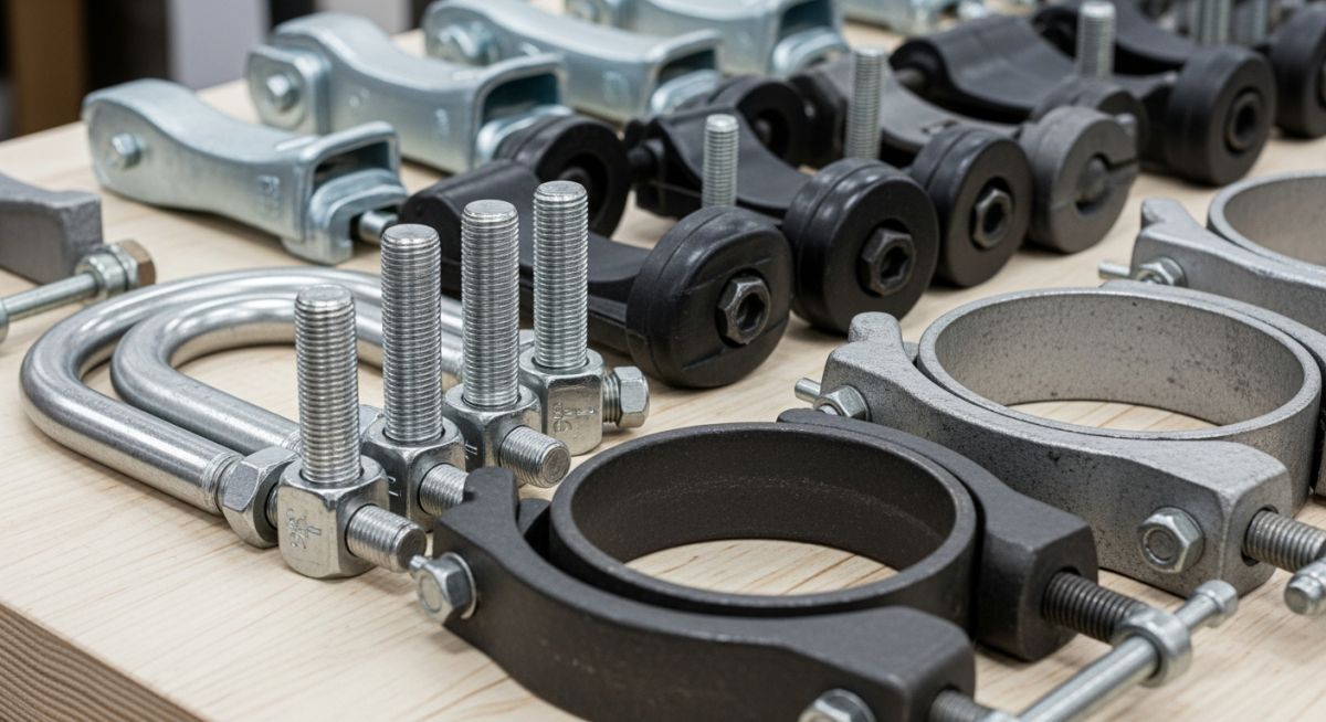
1. Standard Two-Bolt Clamps (MSS SP-58 Type 4)
The standard two-bolt clamp is the workhorse of both the plumbing and industrial piping sectors. Typically manufactured from carbon steel or stainless steel, it consists of two symmetrical halves joined by bolts on either side. It is primarily used for suspending cold or hot insulated lines where thermal expansion is minimal.
2. Three-Bolt Clamps (MSS SP-58 Type 3)
For high-temperature applications, standard two-bolt clamps fall short because the heat causes the pipe to expand radially, which can deform the clamp. The three-bolt clamp solves this by placing a third bolt index point above the pipe. This design accommodates thicker insulation shields and distributes the load more evenly, making it ideal for steam and hot condensate lines operating above 350 degrees Fahrenheit.
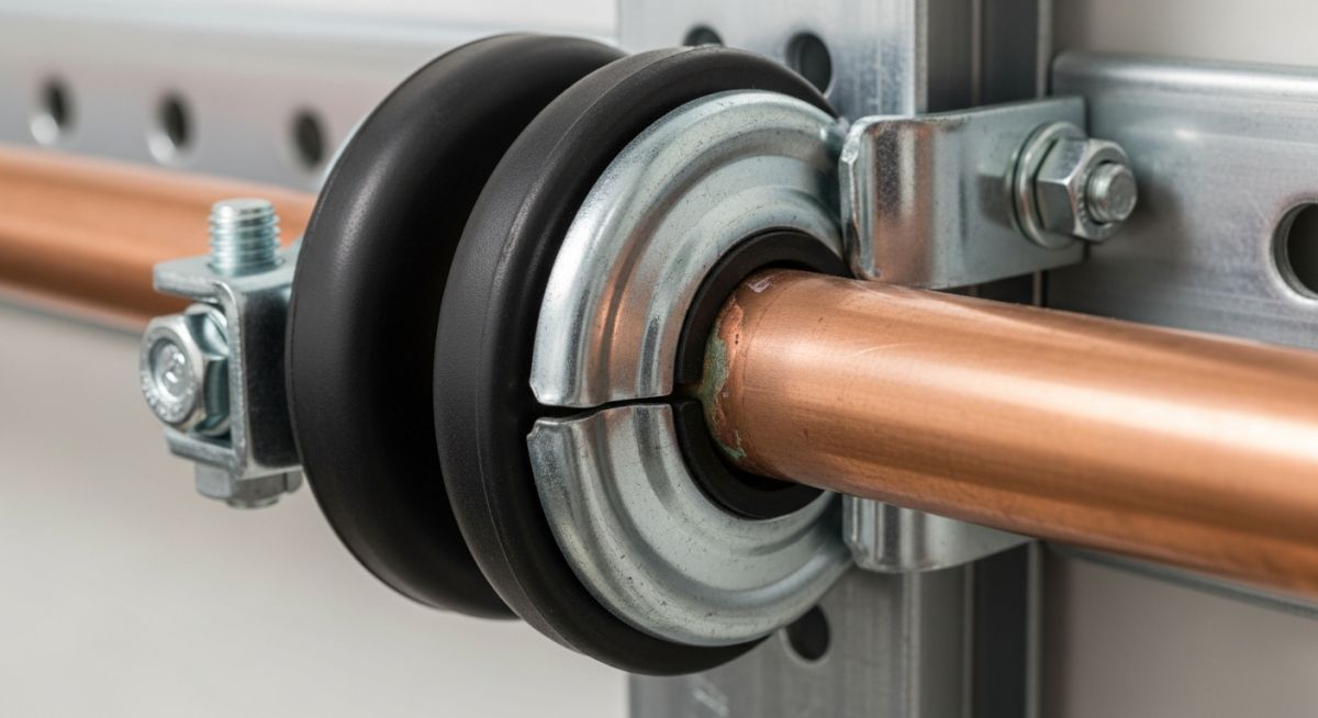
3. Cushioned Clamps (Vibration Isolation)
In systems prone to high-frequency vibration, such as compressor discharge lines or hydraulic power units, metal-to-metal contact leads to rapid fretting wear. Cushioned clamps utilize an elastomeric insert—typically thermoplastic elastomer (TPE), neoprene, or polyurethane—to absorb shock and dampen acoustic noise.
Engineering Calculations: Clamping Force and Bolt Torque
Over-tightening a pipe clamp can crush thin-walled pipes, while under-tightening allows the pipe to slip, causing structural misalignment. To calculate the required bolt torque for a standard two-bolt clamp, we use the following mechanical relationship:
Where:
- Torque is measured in foot-pounds (ft-lbs).
- Friction Factor is typically 0.20 for dry, unlubricated steel bolts, and 0.15 for lubricated steel bolts.
- Target Bolt Tension is the force in pounds required to hold the pipe securely without exceeding the allowable yield strength of the pipe material.
- Nominal Bolt Diameter is measured in inches.
For example, if you are installing a 4-inch carbon steel pipe using a clamp with 0.5-inch unlubricated bolts, and your target tension to resist axial sliding is 3,000 pounds, the calculation is:
Always verify that this clamping force does not exceed the maximum allowable radial crushing load of the pipe, which is calculated using the pipe’s wall thickness and material yield strength under ASME B31.3 guidelines.
The following table outlines the standard load capacities and temperature limits for the most common types of pipe clamps used in industrial applications. All values are based on carbon steel construction unless otherwise specified, in compliance with MSS SP-58.
| Clamp Type | Material Spec | Max Temp (°F) | Max Safe Load (lbs) | MSS SP-58 Type |
|---|---|---|---|---|
| Standard Two-Bolt | ASTM A36 Carbon Steel | 650 | 950 (for 2″ pipe) | Type 4 |
| Heavy Duty Three-Bolt | ASTM A387 Gr 11 Alloy | 1050 | 1,500 (for 2″ pipe) | Type 3 |
| Cushioned Clamp | Steel with TPE Insert | 275 | 400 (for 2″ pipe) | Type 1 (Modified) |
| Standard U-Bolt | ASTM A193 B7 Rod | 750 | 1,200 (for 2″ pipe) | Type 24 |
| Heavy Duty Riser | ASTM A36 Carbon Steel | 650 | 2,500 (for 4″ pipe) | Type 8 |
This matrix maps key engineering entities, physical parameters, and industry standards to help you align your design specifications with regulatory codes.
| Entity / Acronym | Technical Definition | Physical Parameter | Standard Reference |
|---|---|---|---|
| MSS SP-58 | Pipe Hangers and Supports – Materials, Design, Manufacture, Selection, Application, and Installation | Load Rating & Material Limits | MSS Standards |
| ASME B31.3 | Process Piping Code governing chemical, petroleum, and refinery plants | Allowable Stress & Wall Thickness | ASME Codes |
| Galvanic Corrosion | Electrochemical process where one metal corrodes preferentially when in electrical contact with another | Anodic Index Difference | NACE SP0169 |
| Thermal Expansion | The tendency of matter to change its shape, area, and volume in response to a change in temperature | Coefficient of Thermal Expansion | ASME B31.1 Appendix B |
Field Inspection of Various Types of Pipe Clamps
Before commissioning any piping system, a thorough field walkdown is required. Use this checklist to verify that all pipe clamps are installed correctly and will not cause premature system failure.
Pre-Commissioning Clamp Checklist
-
Material Compatibility: Verify that no carbon steel clamps are in direct contact with stainless steel or copper pipes. Check for the presence of isolation pads or liners.
-
Bolt Torque Verification: Ensure all clamp bolts have been tightened using a calibrated torque wrench to the specified engineering values. Look for thread engagement (minimum two threads exposed beyond the nut).
-
Thermal Expansion Clearance: For guide clamps, verify that the design clearance (typically 1/16 inch to 1/8 inch) is maintained to allow axial movement without binding.
-
Riser Clamp Shear Lugs: For vertical riser clamps, confirm that shear lugs are welded to the pipe wall in accordance with ASME Section IX welding procedures to prevent the clamp from slipping down the vertical run.
-
Insulation Protection Shields: On hot insulated lines, verify that the clamp is installed on the outside of an insulation shield (wear saddle) to prevent crushing the insulation material.
Field Case Study: Real-World Application
The Problem: Vibration-Induced Fatigue Failure
At a petrochemical processing facility in Texas, a 3-inch stainless steel hydrocarbon line experienced repeated fatigue cracks at a socket-welded elbow. The line was supported by standard rigid carbon steel U-bolts clamped tightly to structural steel beams.
The rigid clamping restricted the natural thermal expansion of the line, forcing the thermal stress back into the elbow. Furthermore, the metal-to-metal contact between the carbon steel U-bolt and the stainless steel pipe caused localized galvanic pitting, which acted as a stress riser, accelerating the fatigue cracking under pump-induced vibration.
The Solution: Redesign and Clamp Optimization
Our engineering team performed a dynamic stress analysis using CAESAR II software. We recommended replacing the rigid U-bolts with cushioned, slide-guide pipe clamps equipped with thermoplastic elastomer (TPE) liners.
The TPE liners isolated the stainless steel pipe from the carbon steel structure, eliminating galvanic corrosion. The slide-guide design allowed the pipe to expand axially by 0.75 inches during thermal cycles, while the elastomeric cushion absorbed over 85% of the high-frequency vibration generated by the upstream positive displacement pump.
Direct Recommendation: When dealing with vibrating lines or systems subject to thermal cycling, never rely on rigid, unlined clamps. Always perform a thermal flexibility analysis and specify cushioned or slide-guide clamps to protect sensitive weld joints and prevent localized stress concentrations.
Frequently Asked Engineering Questions
What is the primary difference between a two-bolt and a three-bolt pipe clamp?
How do you prevent galvanic corrosion when clamping stainless steel piping?
When should a riser clamp be used instead of a standard hanger clamp?
What role do cushioned pipe clamps play in high-vibration systems?
How does ASME B31.3 govern the selection of pipe clamps?
Can U-bolts be used as tight anchors in high-temperature piping?
===

📚 Recommended Resources: types of pipe clamps
Read these Guides
Related posts:
![Technical infographic showing the workflow of flood risk assessment for data centres, including hydrological inputs and mitigation strategies.]()
Flood Risk Assessment for Data Centres: Engineering Design Guide
![Isometric engineering rendering of a data centre campus featuring flood protection barriers and elevated utility infrastructure for disaster resilience.]()
Flood Protection Level Selection for Mission-Critical Data Centre Infrastructure
![Cross-section diagram of a data centre foundation showing soil strata, pile foundations, and groundwater monitoring wells for geotechnical analysis.]()
Geotechnical Requirements for Data Centres: A Structural Engineering Guide
![Civil 3D interface showing a 3D site grading model with color-coded cut and fill zones for earthwork optimization.]()
Optimizing Cut and Fill Operations Using Civil 3D and GIS
![3D digital terrain model showing site grading, flood protection levels, and cut-fill zones for industrial infrastructure development.]()
Establishing FPL and Estimating Cut Fill Quantities for Site Grading
![3D engineering model showing cut and fill optimization for industrial site grading and earthwork balancing.]()
Cut and Fill Optimization: 8 Engineering Studies for Site Grading