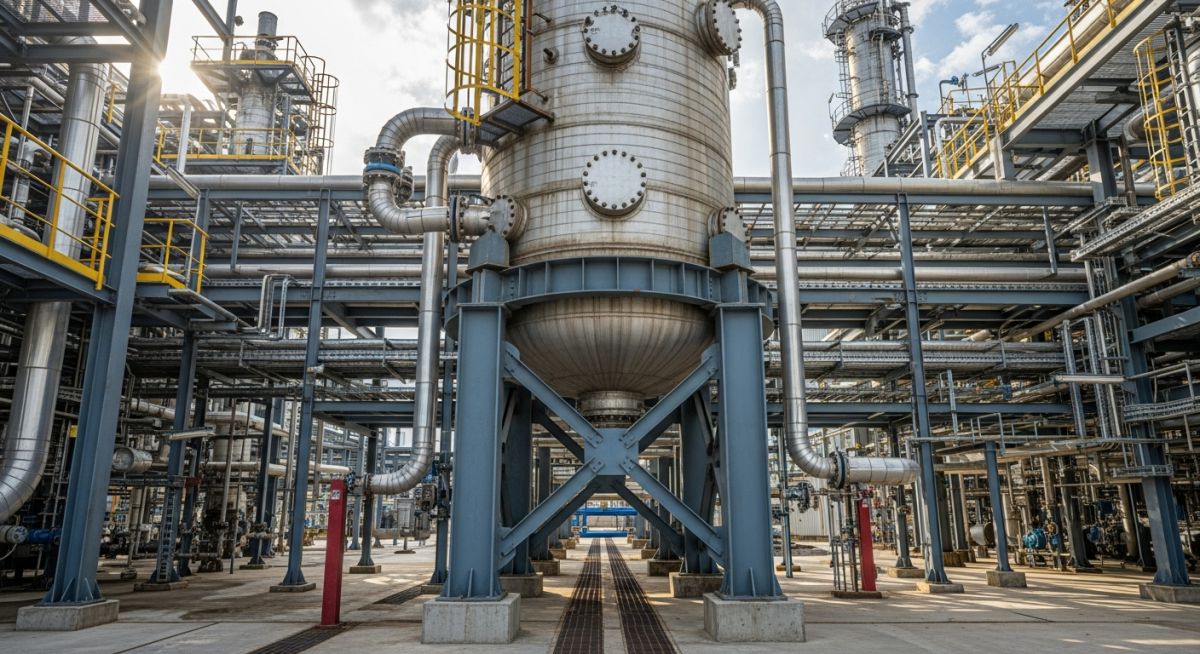
Pressure Vessel Design: ASME Section VIII Standards and Best Practices
In my two decades of experience, I have seen that the integrity of a process plant hinges entirely on the reliability of its pressure vessels. Whether you are dealing with high-pressure gas storage or complex chemical reactors, the margin for error is non-existent. Designing these components requires more than just following a formula; it demands a deep understanding of material fatigue, corrosion allowances, and the interaction between vessel nozzles and connected piping systems.
This guide focuses on the critical path of pressure vessel design, moving beyond basic theory into the practical realities of site-based engineering. We will explore how to interpret code requirements, select appropriate support configurations, and mitigate the risks associated with cyclic loading and thermal expansion.
Key Takeaways for Engineers:
- Mastering the ASME Section VIII Division 1 and 2 distinctions.
- Optimizing support structures to handle seismic and wind loads.
- Implementing accurate corrosion allowance strategies for long-term asset life.
- Ensuring nozzle load compatibility with external piping stress analysis.
Core Technical Principles of Pressure Vessel Design
Pressure Vessel Design: The application of structural mechanics and material science to determine the minimum required thickness of shells and heads, ensuring the vessel maintains structural stability under internal or external pressure conditions.
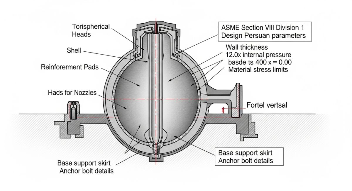
When I approach a new vessel design, the first step is always determining the governing pressure and temperature conditions. Under ASME Section VIII Div 1, the design thickness for a cylindrical shell is calculated using the hoop stress formula: t = (P * R) / (S * E – 0.6 * P), where P is the internal design pressure, R is the internal radius, S is the maximum allowable stress value, and E is the joint efficiency factor.
Field Warning: Joint Efficiency Limitations
Never assume a joint efficiency of 1.0. In practice, the degree of non-destructive examination (NDE) performed on the welds dictates the E value. If you specify spot radiography, your E value drops, forcing a thicker shell and increasing material costs. Always coordinate with the NDE plan early in the design phase.
Beyond the shell, nozzle reinforcement is a frequent point of failure in field installations. When a hole is cut into a shell for a nozzle, the local stress concentration increases significantly. The code requires that the area removed by the opening be replaced by the excess thickness of the nozzle wall, the shell wall, or a reinforcing pad. I always verify that the weld strength of the reinforcing pad is sufficient to transfer the load back into the shell.
Thermal expansion also plays a massive role in vessel support design. If a vessel is operating at high temperatures, the support system—whether it be a skirt, saddle, or leg—must allow for radial and axial growth. Rigidly anchoring a vessel that needs to expand will induce secondary stresses that can lead to buckling or weld cracking at the base ring.
Finally, consider the impact of external loads. Piping connected to the vessel nozzles exerts forces and moments that must be accounted for in the vessel’s local stress analysis. Using WRC 107 or 297 bulletins, I calculate the local stresses at the nozzle-to-shell junction to ensure they remain within the allowable limits defined by the code.
Pressure Vessel Engineering Trade-offs: The critical evaluation of design methodologies, material selection, and support configurations to balance operational safety, manufacturing feasibility, and long-term maintenance costs.
Advantages
- Standardized design codes ensure global safety and interchangeability.
- High-strength alloys allow for thinner walls and reduced weight.
- Advanced NDE techniques provide high confidence in weld integrity.
- Modular support designs facilitate easier field installation and alignment.
- Predictable failure modes allow for effective preventative maintenance.
Disadvantages
- High initial capital expenditure for specialized materials.
- Complex code compliance increases engineering man-hour requirements.
- Strict NDE requirements can lead to significant project delays.
- Thermal expansion constraints often require expensive expansion joints.
- Corrosion allowance adds dead weight and increases structural steel costs.
Industrial Pressure Vessel Deployment: The strategic implementation of pressurized containment systems across diverse sectors, tailored to specific fluid properties, temperature regimes, and environmental safety requirements.
Refinery Hydroprocessing Units
These vessels operate under extreme hydrogen partial pressures and high temperatures, requiring specialized chrome-moly steels to prevent hydrogen embrittlement. The design must account for severe cyclic loading during startup and shutdown phases, necessitating rigorous fatigue analysis per ASME Section VIII Div 2.
Cryogenic Liquefied Gas Storage
Storage vessels for LNG or liquid nitrogen require materials with high fracture toughness at sub-zero temperatures, typically utilizing stainless steel or 9% nickel steel. The support system must incorporate thermal breaks to prevent cold transfer to the structural steel foundation, which could cause brittle failure of the support members.
Chemical Reactor Vessels
Reactors often involve complex internal agitators and heating jackets, creating non-uniform stress distributions across the shell. The design must integrate nozzle reinforcement with internal baffle supports, ensuring that the vessel can withstand both the internal pressure and the mechanical torque generated by the mixing process.
Selecting the correct material and design pressure rating is the foundation of safe vessel engineering. In my experience, engineers often overlook the interaction between the allowable stress values defined in ASME Section VIII Division 1 and the specific corrosive nature of the process fluid. The table below outlines standard material grades and their typical application limits, providing a baseline for initial design iterations.
When reviewing these parameters, always ensure that the design temperature accounts for potential process excursions. Using a material with a higher allowable stress at elevated temperatures can significantly reduce wall thickness, thereby lowering the total weight and cost of the vessel support structure. However, this must be balanced against the increased cost of high-alloy materials and the potential for brittle fracture at low-temperature service conditions.
| Material Grade | ASME Standard | Max Temp (F) | Primary Application |
|---|---|---|---|
| SA-516 Gr 70 | ASME II-A | 850 | General Carbon Steel Vessels |
| SA-240 316L | ASME II-A | 1500 | Corrosive/Chemical Service |
| SA-387 Gr 11 | ASME II-A | 1100 | High Temp Hydroprocessing |
Always verify the latest edition of the ASME Boiler and Pressure Vessel Code, as allowable stress values are subject to periodic updates based on metallurgical research and failure analysis data. Never extrapolate values beyond the code-specified temperature limits without formal engineering justification and client approval.
The following matrix maps critical engineering entities to their respective regulatory standards and physical design constraints. This mapping is essential for maintaining traceability during the design review process, especially when dealing with complex multi-vessel systems where piping loads and thermal expansion must be integrated into the vessel support design.
By standardizing these inputs, we ensure that the design team remains aligned with the project’s technical specifications. This matrix serves as a quick-reference guide for junior engineers to identify which code section governs specific components, such as nozzles, flanges, or internal support rings, ensuring that no critical design element is overlooked during the stress analysis phase.
| Entity | Standard | Key Parameter |
|---|---|---|
| Shell Thickness | ASME VIII-1 | Internal Pressure |
| Nozzle Loads | WRC 107/297 | Moment/Force |
| Vessel Supports | ASCE 7 | Seismic/Wind Load |
The integration of WRC (Welding Research Council) bulletins with standard ASME calculations is a best practice for nozzle reinforcement design. These documents provide the necessary empirical data to handle local stresses that standard shell formulas cannot address, preventing fatigue-related failures in high-cycle service environments.
Before a pressure vessel is commissioned, a rigorous site verification process is mandatory to ensure that the as-built condition matches the design intent. In my experience, most field issues arise from discrepancies between the piping isometric drawings and the actual nozzle orientation on the vessel. This checklist provides a structured approach to verifying critical installation parameters.
- Foundation Leveling: Verify that the base plate is perfectly level using a precision laser level to prevent uneven stress distribution on the vessel skirt or legs.
- Nozzle Orientation: Confirm that all nozzle centerlines match the approved piping layout drawings within the tolerance specified in ASME Section VIII.
- Anchor Bolt Tension: Ensure that anchor bolts are tightened to the specified torque values to accommodate thermal expansion and wind-induced overturning moments.
- Grounding Continuity: Check that the vessel is properly grounded to the plant grid to prevent static electricity buildup and potential ignition hazards.
- Insulation Clearance: Verify that there is sufficient clearance around manways and inspection ports to allow for future maintenance and periodic NDT testing.
Documenting these checks is not just a regulatory requirement; it is a critical safety measure. If any deviation is found, it must be formally addressed through a Management of Change (MOC) process before the vessel is pressurized. Always maintain a copy of the final inspection report in the vessel’s permanent maintenance file for future reference during statutory inspections.
Problem: Excessive Nozzle Loading in High-Temperature Service
- Thermal expansion of connected piping exceeded the allowable nozzle load limits defined in the original design specification.
- The vessel shell showed signs of localized deformation near the nozzle-to-shell junction during the first heat-up cycle.
- Lack of flexible piping supports resulted in high bending moments being transferred directly to the vessel nozzle.
Outcome: Successful Mitigation and Structural Integrity Restoration
- Implemented a spring-hanger support system to absorb thermal expansion and reduce the load on the nozzle.
- Performed a finite element analysis (FEA) to verify that the modified load configuration remained within the allowable stress limits of the vessel shell.
- Installed a reinforcement pad to distribute the localized stresses more effectively across the shell wall.
- Achieved a 40% reduction in measured nozzle stress during subsequent operational testing.
This case highlights the importance of considering piping flexibility during the early stages of vessel design. If the piping layout is not coordinated with the vessel support design, the resulting nozzle loads can lead to premature failure. I recommend conducting a comprehensive stress analysis for all critical nozzles in high-temperature or high-pressure applications to avoid these costly field modifications.
Frequently Asked Engineering Questions
What is the primary difference between ASME Section VIII Division 1 and Division 2?
The primary distinction lies in the design philosophy and the level of analysis required for construction. Division 1 is based on design-by-rule, which is simpler but often results in thicker, heavier vessels. Division 2 utilizes design-by-analysis, allowing for more precise optimization of wall thickness through advanced stress calculations.
- Division 1 is ideal for standard, lower-pressure applications where simplicity is preferred.
- Division 2 is preferred for high-pressure or high-temperature service where weight reduction is critical.
- Division 2 requires more rigorous material testing and NDT (Non-Destructive Testing) documentation.
How do I determine the correct corrosion allowance for a vessel?
Corrosion allowance is determined by the expected service life of the vessel and the chemical aggressiveness of the process fluid. It is not a fixed value but a design parameter that must be specified by the process engineering team based on historical data or material compatibility studies.
- Standard allowances typically range from 1.5mm to 3mm depending on the fluid.
- Always account for the “worst-case” corrosion rate expected during the vessel’s design life.
- If the fluid is highly corrosive, consider using a corrosion-resistant alloy (CRA) cladding instead of a large corrosion allowance.
When is a vessel support skirt required versus leg supports?
The choice between a skirt and leg supports depends on the vessel’s height, diameter, and the magnitude of lateral loads such as wind or seismic forces. Skirts are generally preferred for tall, vertical vessels because they provide a continuous, uniform load distribution to the foundation.
- Leg supports are suitable for smaller, shorter vessels where the bending moment at the base is manageable.
- Skirts are essential for tall towers to prevent buckling and to provide a stable base for thermal expansion.
- Always perform a structural analysis to compare the overturning moments for both support types before finalizing the design.
What is the significance of the joint efficiency factor in ASME VIII?
The joint efficiency factor (E) represents the quality and extent of the non-destructive examination (NDE) performed on the vessel’s welded joints. A higher efficiency factor allows for a thinner shell, but it requires more stringent inspection protocols during fabrication.
- Full radiography (RT) allows for an efficiency factor of 1.0.
- Spot radiography or no radiography results in lower factors, requiring thicker walls to compensate for potential weld defects.
- Always balance the cost of NDE against the cost of additional material thickness when selecting the joint efficiency.
How do I handle nozzle reinforcement for large openings?
Large openings in a pressure vessel shell create stress concentrations that must be mitigated using reinforcement pads or increased shell thickness. The area replacement method, as defined in ASME Section VIII, is the standard approach for ensuring that the shell maintains its structural integrity.
- The reinforcement area must be equal to or greater than the area removed by the opening.
- Reinforcement pads must be properly welded to the shell and nozzle to ensure load transfer.
- For very large openings, consider using a self-reinforced nozzle forging to minimize stress concentrations.
What are the common causes of pressure vessel failure in service?
Pressure vessel failures are typically caused by a combination of fatigue, corrosion, and improper operational practices. Understanding these failure modes is critical for developing effective inspection and maintenance programs.
- Fatigue failure often occurs at nozzle junctions due to cyclic pressure or thermal loads.
- Corrosion-related thinning can lead to localized wall failure if not monitored through regular thickness gauging.
- Over-pressurization due to relief valve failure is a common cause of catastrophic rupture.
- Brittle fracture can occur during cold start-up if the material’s toughness is not properly evaluated.
📚 Recommended Resources: Pressure Vessel Design
Read these Guides
🎓 Advanced Training

Complete Course on
Piping Engineering
Check Now
Key Features
- 125+ Hours Content
- 500+ Recorded Lectures
- 20+ Years Exp.
- Lifetime Access
Coverage
- Codes & Standards
- Layouts & Design
- Material Eng.
- Stress Analysis
