Learn to perform accurate WRC 107 and WRC 297 nozzle stress analysis in Caesar II. Optimize your piping design for ASME code compliance today.
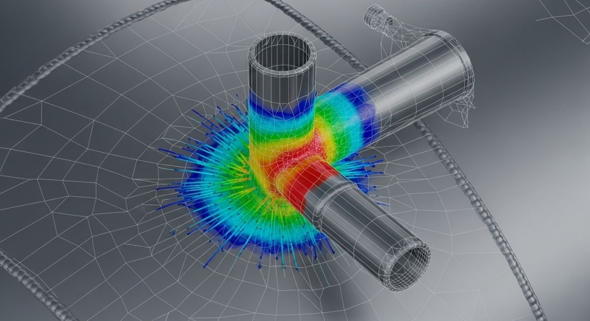
Learn to perform accurate WRC 107 and WRC 297 nozzle stress analysis in Caesar II. Optimize your piping design for ASME code compliance today.
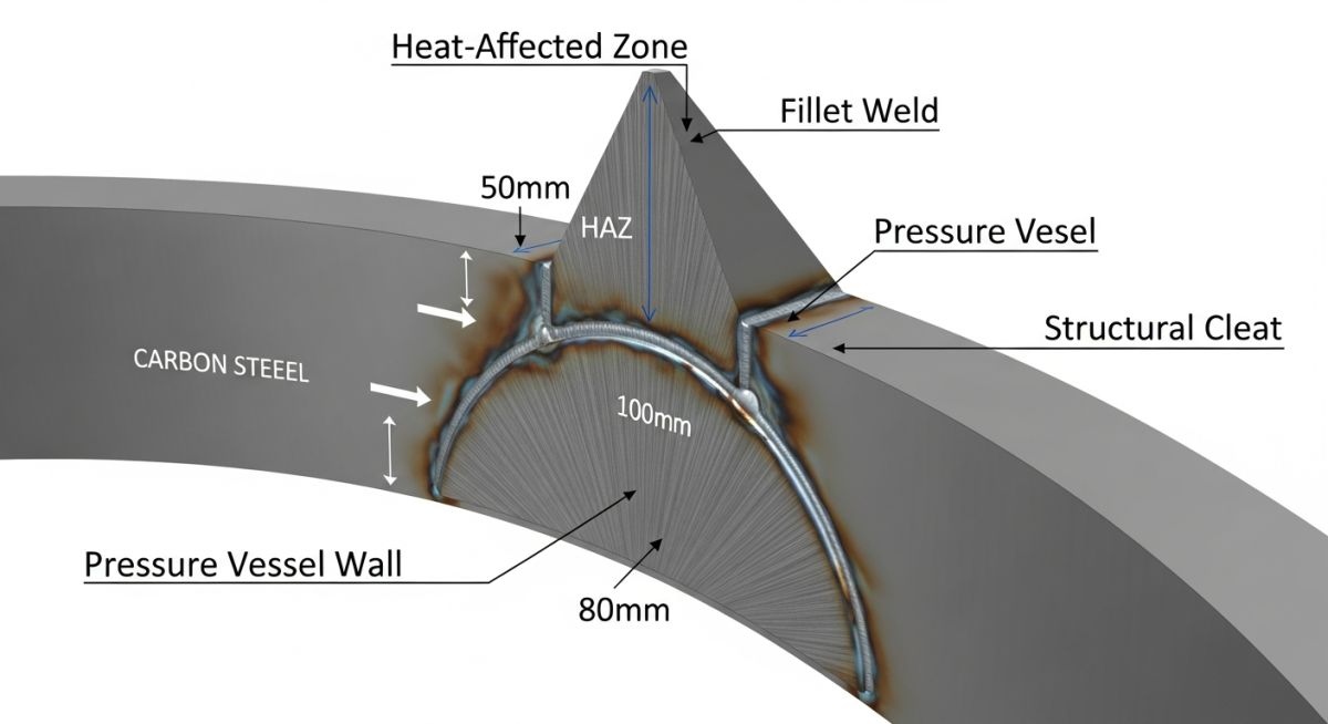
Master the design, welding, and load-bearing requirements for Pressure Vessel Clips. Learn how to ensure structural integrity per ASME Section VIII standards.
Master the design and installation of Pressure Vessel Clips. Learn load distribution, welding standards, and stress analysis for reliable structural attachments.
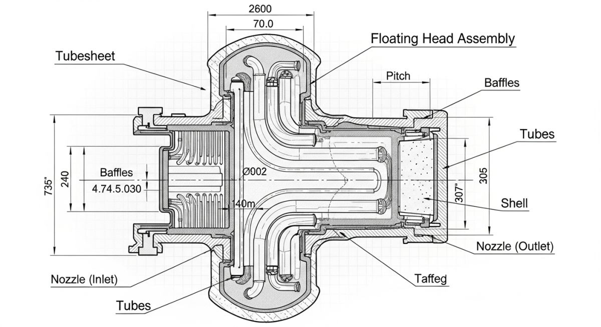
Master the technical review of Shell and Tube Heat Exchanger drawings. Follow this expert checklist to ensure ASME compliance and operational safety.
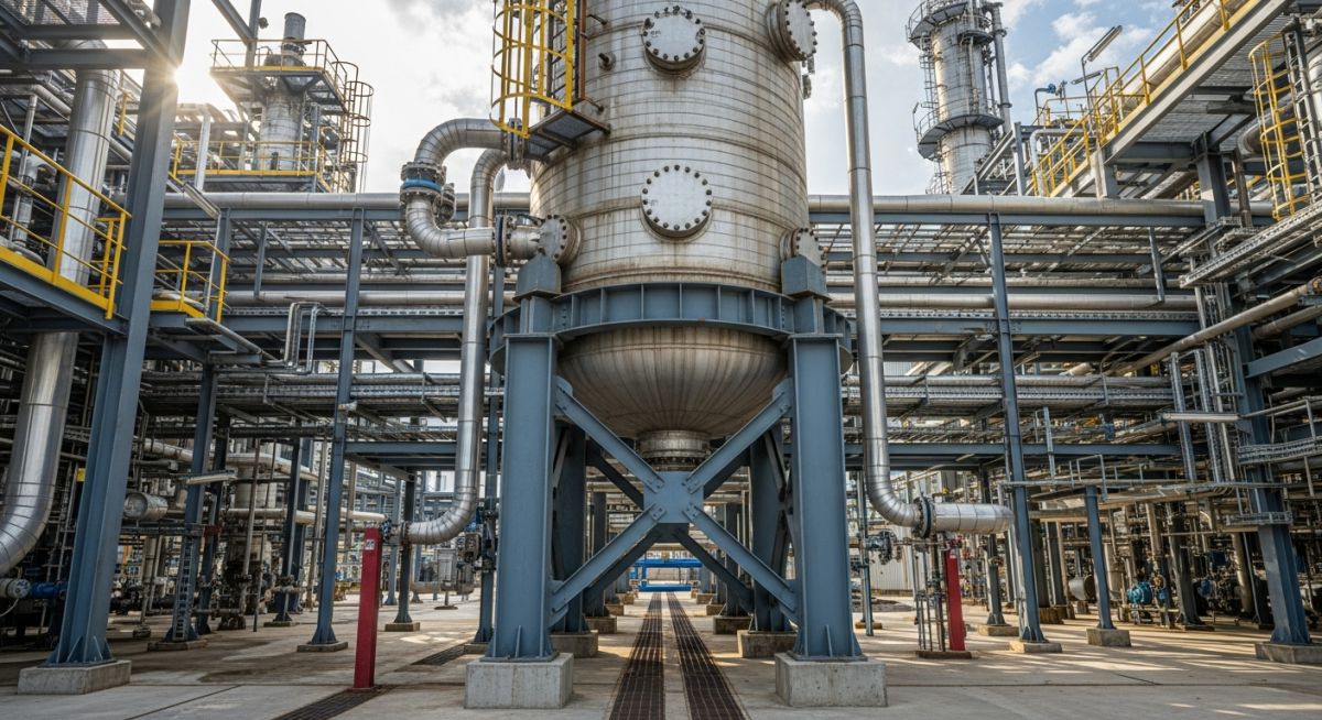
Master Pressure Vessel Design with this guide on ASME Section VIII, material selection, support types, and safety calculations for industrial piping systems.
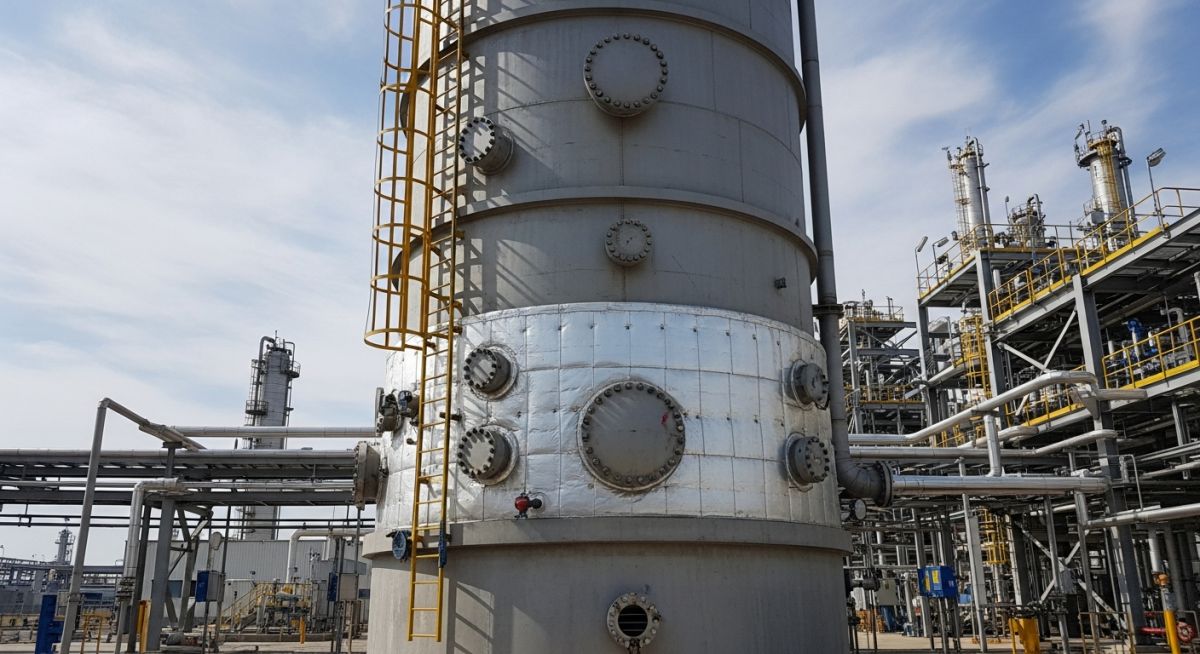
Learn the critical engineering principles for Pressure Vessel Design, focusing on ASME Section VIII compliance for safe pressure and temperature management.
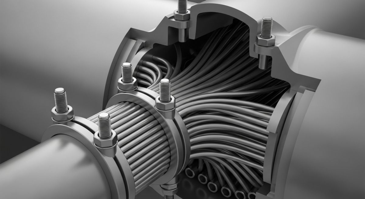
Learn how Collar Bolts ensure safe, efficient maintenance for removable heat exchanger bundles. Optimize your turnaround procedures with these critical mechanical components.
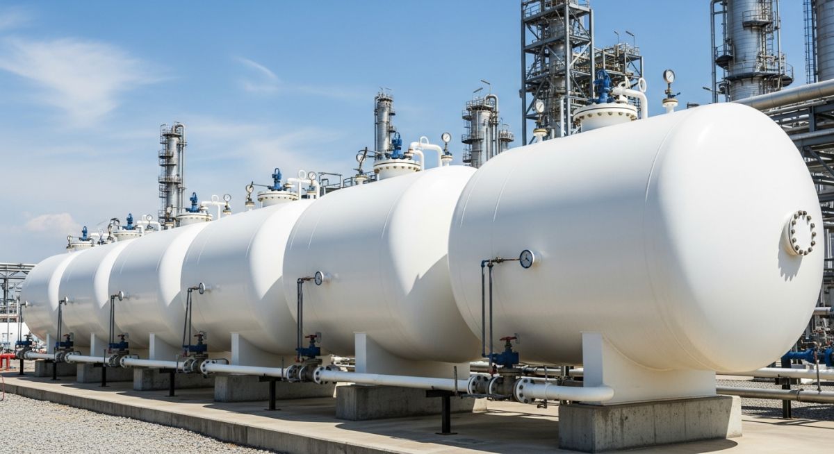
Learn about LPG storage tanks, including their types, selection criteria, engineering specifications, and step-by-step design calculations.
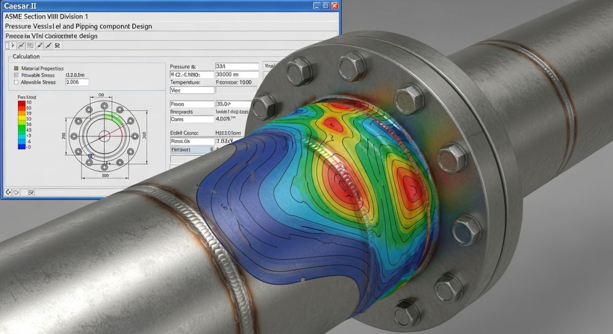
Learn how to perform ASME Section VIII flange leakage checking in Caesar II to ensure piping system integrity and prevent hazardous leaks.
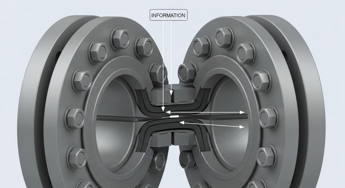
Learn why gasket m and y factors are critical for leak-free bolted flange joint design under ASME Section VIII standards.
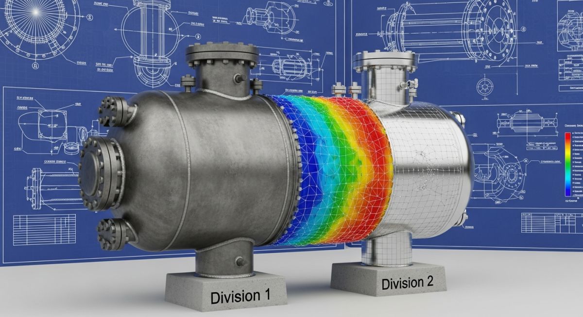
Learn the key differences between ASME Section VIII Division 1 and Division 2 pressure vessel design codes, including design margins and costs.
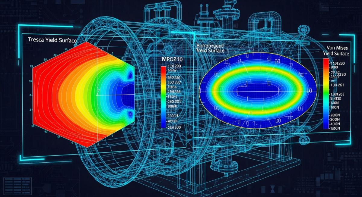
Compare Tresca and Von Mises yield criteria for piping and pressure vessel design. Learn when to apply each stress theory accurately.