Mastering Pressure Vessel Design: ASME Section VIII Compliance
In my two decades of field experience, I have learned that the intersection of pressure and temperature is where most mechanical integrity failures originate. Designing a vessel is not merely about selecting a plate thickness; it is about managing the complex interplay between hoop stress, longitudinal stress, and the thermal expansion coefficients of the chosen metallurgy.
Whether you are dealing with cryogenic storage or high-temperature catalytic cracking, the governing codes provide the safety margins necessary to prevent catastrophic rupture. This guide breaks down the essential calculations and regulatory requirements you need to ensure your equipment remains compliant and, more importantly, safe for your operators.
Key Takeaways for Engineers
- Understanding the Maximum Allowable Working Pressure (MAWP) versus design pressure.
- Applying ASME Section VIII Division 1 and 2 rules for shell thickness.
- Managing thermal stress through proper nozzle reinforcement and support selection.
- Ensuring material compatibility with process fluids under cyclic temperature conditions.
Core Principles of Pressure Vessel Design
Pressure Vessel Design: The rigorous engineering process of calculating wall thickness and structural reinforcement based on internal pressure, temperature, and material allowable stress values defined by the ASME Boiler and Pressure Vessel Code.
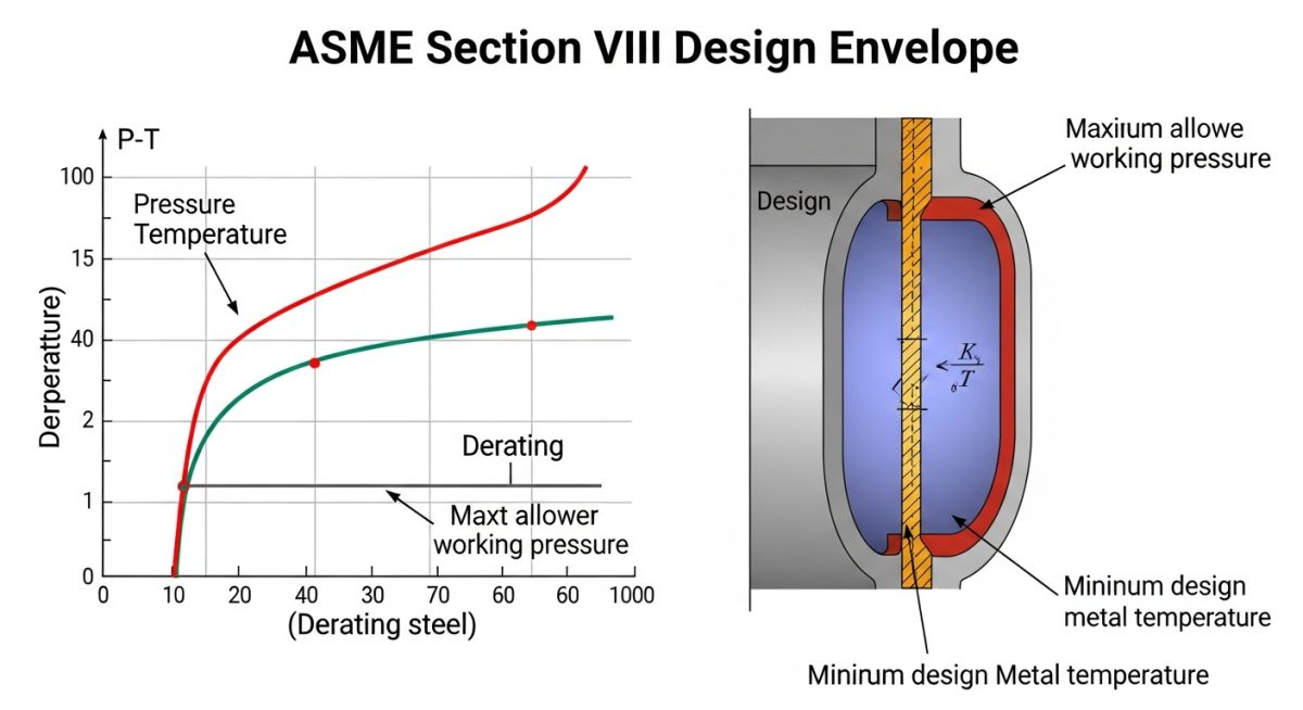
When I approach a new vessel design, the first step is always establishing the design conditions. The design pressure must be at least the maximum operating pressure plus a margin, typically 10% or 25 psi, whichever is greater. However, the temperature is equally critical. As temperature increases, the allowable stress value (S) of the material decreases, which directly forces an increase in the required wall thickness (t).
The fundamental formula for a thin-walled cylindrical shell under internal pressure is t = (P * R) / (S * E – 0.6 * P), where P is the design pressure, R is the internal radius, S is the maximum allowable stress, and E is the joint efficiency. In my experience, junior engineers often overlook the joint efficiency factor (E). If you are performing full radiography on your welds, E can be 1.0, but if you are using spot radiography or no radiography, this value drops significantly, forcing a thicker, more expensive wall.
Field Warning: The Corrosion Allowance Trap
Never forget to add the corrosion allowance (CA) to your calculated thickness. If your process involves sour gas or high-chloride environments, the CA must be based on the expected service life of the vessel, not just a standard 3mm default. I have seen vessels fail prematurely because the design team failed to account for localized pitting rates in their initial thickness calculations.
Thermal management is the second pillar of design. When a vessel operates at high temperatures, we must account for thermal expansion. If the vessel is constrained by rigid piping or fixed supports, the resulting thermal stresses can exceed the yield strength of the nozzle necks. I always recommend a thorough ASME B31.3 stress analysis for any nozzle connected to a vessel operating above 250 degrees Celsius.
Finally, consider the impact of external pressure. If your vessel is subject to vacuum conditions, the design shifts from simple hoop stress to buckling analysis. The ASME Section VIII provides specific charts for determining the required thickness to prevent collapse under external pressure, which is a non-linear calculation that requires precise material property inputs.
ASME Compliance Benefits: The implementation of standardized design protocols ensures global interoperability, predictable safety margins, and simplified regulatory approval for high-pressure industrial assets.
Advantages
- Standardized safety factors provide predictable failure modes.
- Global acceptance of ASME stamps facilitates international trade.
- Extensive material databases reduce the need for custom testing.
- Clear documentation requirements improve long-term maintenance tracking.
- Established inspection intervals ensure ongoing mechanical integrity.
Disadvantages
- Conservative design rules often lead to over-engineered, heavy vessels.
- High cost of specialized materials for extreme temperature service.
- Rigid code requirements can limit innovative, lightweight geometries.
- Extensive documentation and NDT requirements increase project lead times.
- Complexity of Division 2 analysis requires advanced FEA expertise.
Industrial Pressure Applications: The deployment of pressure vessels across diverse sectors requires tailored design approaches to handle specific fluid properties, thermal cycles, and environmental stressors.
High-Pressure Hydrogen Storage
Hydrogen service requires specialized metallurgy to prevent hydrogen embrittlement. Designers must select low-alloy steels and implement strict welding procedures to ensure the vessel can withstand high-pressure cycles without crack propagation.
Cryogenic Liquefied Natural Gas (LNG) Vessels
Operating at temperatures as low as minus 162 degrees Celsius, these vessels utilize stainless steel or nickel-alloy shells. The design focus is on thermal insulation and managing the extreme contraction of the inner vessel relative to the outer jacket.
Petrochemical Reactor Vessels
These vessels operate under combined high-pressure and high-temperature conditions, often involving corrosive catalysts. Design involves complex nozzle reinforcement and internal cladding to protect the base metal from chemical attack while maintaining structural load-bearing capacity.
When evaluating the mechanical integrity of a pressure vessel, engineers must strictly adhere to the design limits defined in ASME Section VIII Division 1. The relationship between internal pressure and operating temperature dictates the selection of materials, specifically regarding their allowable stress values and toughness requirements. As temperatures rise, the yield strength of carbon and low-alloy steels typically decreases, necessitating a thicker wall to maintain the same pressure rating.
The following table outlines the critical design parameters that must be verified during the initial sizing phase. These values are derived from the material properties listed in Section II Part D of the ASME code. It is imperative to note that the Maximum Allowable Working Pressure (MAWP) must never be exceeded during normal operation, and the design temperature must account for the maximum expected process fluid temperature plus a safety margin for potential process upsets or thermal excursions.
| Parameter | Standard Reference | Design Consideration |
|---|---|---|
| MAWP | ASME VIII Div 1 UG-98 | Maximum pressure at top of vessel |
| Design Temperature | ASME VIII Div 1 UG-20 | Metal temperature under operating conditions |
| Allowable Stress | ASME II Part D | Temperature-dependent material strength limit |
| Corrosion Allowance | ASME VIII Div 1 UG-25 | Added thickness for service life degradation |
By cross-referencing these parameters with the specific service fluid, engineers can determine if the vessel requires post-weld heat treatment (PWHT) or impact testing to ensure brittle fracture resistance at low temperatures. Always verify that the selected material grade remains ductile across the entire operating range.
The complexity of modern pressure vessel design requires a systematic mapping of physical entities to their corresponding regulatory and mechanical constraints. This matrix serves as a technical bridge between the physical components of the vessel and the governing standards that dictate their structural requirements. By aligning these entities, we ensure that every weld, nozzle, and shell section complies with the rigorous safety standards required for high-pressure industrial environments.
Engineers should utilize this matrix during the design review process to confirm that all critical components have been evaluated against the appropriate ASME code sections. This mapping helps in identifying potential gaps in documentation or design verification, particularly when dealing with complex geometries or extreme temperature fluctuations that may affect the structural integrity of the vessel over its intended service life.
| Component | Acronym | Standard |
|---|---|---|
| Pressure Vessel | PV | ASME VIII |
| Post Weld Heat Treatment | PWHT | ASME UW-40 |
| Non-Destructive Examination | NDE | ASME V |
| Minimum Design Metal Temp | MDMT | ASME UCS-66 |
Consistent application of these standards ensures that the vessel remains within its safe operating envelope. Any deviation from these specifications requires a formal Management of Change (MOC) process to evaluate the impact on the vessel’s overall mechanical integrity and safety profile.
Verification of pressure vessel design is a multi-stage process that requires meticulous attention to detail. Before any fabrication begins, the design must be validated against the specific process requirements and the governing ASME Boiler and Pressure Vessel Code. This checklist provides a structured approach to ensuring that all critical design factors, including pressure, temperature, and material compatibility, have been addressed.
-
Design Pressure Alignment: Confirm that the design pressure exceeds the maximum operating pressure by at least 10 percent or 25 psi, whichever is greater, to account for relief valve set points. -
Temperature Extremes: Verify that the design temperature covers the full range of process conditions, including startup, shutdown, and potential emergency cooling scenarios. -
Material Toughness: Ensure that the Minimum Design Metal Temperature (MDMT) is calculated per ASME UCS-66 to prevent brittle fracture. -
Corrosion Allowance: Validate that the specified corrosion allowance is sufficient for the intended 20-year design life based on the chemical composition of the process fluid. -
Nozzle Reinforcement: Check that all nozzle openings are properly reinforced according to ASME UG-37 to maintain shell integrity.
Site verification is equally important. During the installation phase, inspectors must confirm that the nameplate data matches the design calculations and that all pressure relief devices are calibrated to the correct set pressure. Any discrepancies found during this stage must be resolved before the vessel is introduced to service. Regular audits of these parameters ensure that the vessel continues to operate within its safe design limits throughout its lifecycle.
Problem: Unexpected Brittle Fracture Risk
A high-pressure separator experienced a process upset that caused the internal metal temperature to drop significantly below the original design specifications.
- Operating temperature dropped to -40 degrees Celsius during a rapid depressurization event.
- Original material specification did not account for low-temperature impact testing requirements.
- Vessel shell thickness was insufficient to handle the thermal shock stresses induced by the rapid cooling.
- Lack of proper insulation on the vessel support skirts exacerbated the thermal gradient.
Outcome: Successful Mitigation and Compliance
The engineering team implemented a comprehensive remediation strategy to restore the vessel to a safe operating state.
- Installed automated thermal control valves to prevent rapid temperature drops during depressurization.
- Applied specialized cryogenic insulation to the vessel shell and support structures.
- Performed a fitness-for-service assessment per API 579 to validate the remaining structural integrity.
- Updated the operating procedures to include strict temperature ramp-up and ramp-down limits.
My recommendation for similar scenarios is to always perform a thorough HAZOP study that includes extreme temperature scenarios. Designing for the worst-case thermal condition is far more cost-effective than performing field retrofits after a near-miss incident.
Frequently Asked Engineering Questions
How does temperature affect allowable stress in ASME VIII?
- Designers must use the maximum expected metal temperature to select the appropriate allowable stress.
- Operating at higher temperatures requires thicker walls to compensate for reduced material strength.
- Creep-rupture properties become the limiting factor for vessels operating in high-temperature regimes.
What is the significance of MDMT in vessel design?
- Materials exhibit a transition from ductile to brittle behavior as temperatures drop.
- Impact testing is required if the operating temperature falls below the exemption curves in the code.
- Proper MDMT calculation prevents catastrophic failure during cold-weather startup or depressurization.
How is MAWP determined for an existing vessel?
- Account for current wall thickness measurements obtained through ultrasonic testing.
- Subtract the estimated corrosion rate from the remaining service life.
- Recalculate the pressure rating using the weakest component, such as the shell or nozzle reinforcement.
When is Post Weld Heat Treatment (PWHT) required?
- Mandatory for certain material thicknesses and P-number classifications.
- Required for services prone to stress corrosion cracking, such as amine or caustic environments.
- Helps ensure the vessel meets the toughness requirements for its intended service temperature.
What role does corrosion allowance play in design?
- Calculated based on the expected corrosion rate of the process fluid.
- Must be included in all pressure-containing wall thickness calculations.
- Regular inspections are necessary to monitor the actual corrosion rate against the design allowance.
How do relief valves protect pressure vessels?
- Sizing must account for all potential overpressure sources, including fire and process control failures.
- Must be maintained and tested periodically per API 576.
- The set pressure must be at or below the MAWP of the vessel to ensure safety.
📚 Recommended Resources: Pressure Vessel Design
Read these Guides
🎓 Advanced Training


Complete Course on
Piping Engineering
Check Now
Key Features
- 125+ Hours Content
- 500+ Recorded Lectures
- 20+ Years Exp.
- Lifetime Access
Coverage
- Codes & Standards
- Layouts & Design
- Material Eng.
- Stress Analysis
