Pressure Vessel Nozzles: Complete Guide to Types, Loads, and Design
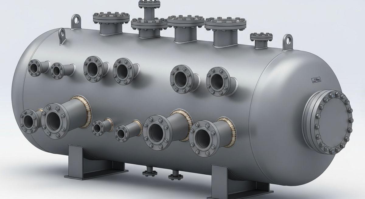
In my 20 years of piping engineering, I have seen many young engineers treat pressure vessel nozzles as simple pipe stubs welded onto a shell. This is a dangerous mistake. A nozzle is a major structural discontinuity in a pressure-retaining shell. When you cut a hole in a vessel to insert a nozzle, you remove a significant portion of the load-bearing metal. Restoring that strength while managing the massive thermal and mechanical forces from connected piping is one of the most challenging aspects of pressure vessel design.
Whether you are designing a high-pressure reactor or a simple storage drum, understanding how these connections behave under pressure and external piping loads is key to preventing catastrophic field failures. In this guide, I will share my practical field experience and walk you through the core design principles, reinforcement calculations, and load evaluation methods that keep these systems operating safely.
- Nozzle design is governed by ASME Section VIII Division 1 UG-37 area replacement rules.
- External piping loads must be analyzed using WRC 107/537 or finite element analysis (FEA).
- Proper reinforcement pad selection prevents localized shell buckling and fatigue failure.
Complete Course on
Piping Engineering
Check Now
Key Features
- 125+ Hours Content
- 500+ Recorded Lectures
- 20+ Years Exp.
- Lifetime Access
Coverage
- Codes & Standards
- Layouts & Design
- Material Eng.
- Stress Analysis
How Do Pressure Vessel Nozzles Maintain Structural Integrity?
Pressure Vessel Nozzles Reinforcement: The process of restoring the cross-sectional area removed from a vessel shell by adding extra material around the opening in compliance with ASME Section VIII Division 1 UG-37.
When designing pressure vessel nozzles, we must account for two primary loading conditions: internal/external pressure and external piping loads. The shell thickness is calculated based on hoop stress, but when we cut a hole for a nozzle, the stress lines are diverted, creating a high stress concentration around the opening.
The Area Replacement Method (ASME UG-37)
The fundamental principle of nozzle design under ASME Section VIII Division 1 is the Area Replacement Method. Simply put, the cross-sectional area of metal removed by the opening must be compensated for by excess metal available in the vessel wall, the nozzle wall, and any added reinforcement pads.
The required reinforcement area (A) is calculated as:
Where:
- d: Finished diameter of the circular opening in its corroded condition.
- t_r: Required thickness of a seamless shell or head computed by code formulas.
- F: Correction factor (typically 1.0 for most nozzle configurations).
The available area (A_{available}) is the sum of the excess thickness in the vessel shell (A_1), the excess thickness in the nozzle wall (A_2), the weld metal area (A_3), and the area of any reinforcing pad (A_4). If A_{available} ge A, the nozzle is self-reinforced. If not, we must add a reinforcing pad (repad) or increase the nozzle neck thickness.
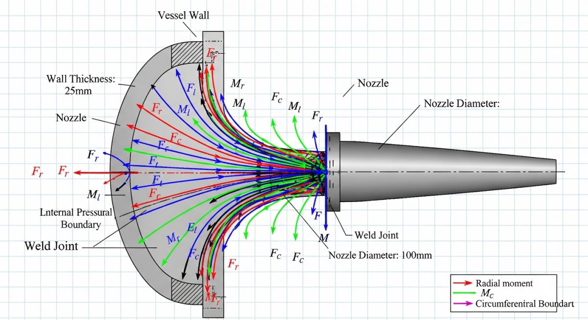
Evaluating External Piping Loads (WRC 107 / WRC 537)
Internal pressure is only half the battle. Connected piping expands and contracts due to thermal cycles, exerting forces and moments on the nozzle. We evaluate these local stresses using Welding Research Council (WRC) Bulletins 107, 297, or 537. These bulletins provide semi-analytical methods to calculate local membrane and bending stresses in the vessel shell caused by external radial loads, longitudinal bending, circumferential bending, and torsional moments.
Never assume a standard reinforcement pad solves all nozzle load issues. While a repad satisfies the UG-37 area replacement rule for internal pressure, it does very little to increase the nozzle’s resistance to external piping moments. In fact, heavy piping loads on a repad can cause localized stress concentrations at the pad-to-shell fillet weld, leading to fatigue cracking over time.
Standard Dimensions for Pressure Vessel Nozzles
Nozzle Dimensional Standards: The standardized physical parameters and wall thicknesses required to satisfy ASME B16.5 and ASME B16.47 flange ratings for pressure vessel connections.
In my projects, we use standardized dimensions to streamline procurement and fabrication. The table below outlines typical nozzle neck schedules and minimum reinforcement pad widths for common nominal pipe sizes (NPS) based on standard engineering practices.
| Nominal Size (NPS) | Flange Rating (Class) | Min Nozzle Neck Schedule | Typical Repad OD (mm) | ASME Reference |
|---|---|---|---|---|
| 2″ (DN 50) | 150# / 300# | Sch 80S / XS | 115 | ASME B16.5 |
| 4″ (DN 100) | 150# / 300# | Sch 40S / STD | 220 | ASME B16.5 |
| 6″ (DN 150) | 300# | Sch 40S / STD | 320 | ASME B16.5 |
| 8″ (DN 200) | 300# | Sch 40S / STD | 410 | ASME B16.5 |
| 12″ (DN 300) | 300# | Sch STD | 610 | ASME B16.5 |
| Technical Entity | Acronym | Physical Parameter | Standard Reference |
|---|---|---|---|
| Area Replacement Method | ARM | Cross-sectional Area (A) | ASME Sec VIII Div 1 UG-37 |
| Local Stress Analysis | LSA | Forces (P, V_C, V_L) & Moments (M_T, M_C, M_L) | WRC Bulletin 107 / 537 |
| Flange Rating | FR | Pressure-Temperature Rating | ASME B16.5 |
| Reinforcement Pad | Repad | Pad Width & Thickness | ASME Sec VIII Div 1 UG-37 |
| Weld Joint Efficiency | E | Dimensionless Factor (0.7 to 1.0) | ASME Sec VIII Div 1 UW-12 |
Field Inspection of Pressure Vessel Nozzles
Nozzle Quality Control: The systematic field verification protocol executed to confirm weld profile compliance, reinforcement pad pneumatic testing, and dimensional tolerances before hydrotest.
During my site visits, I always carry a checklist to ensure the fabrication shop or field installers do not cut corners. A poorly welded nozzle or a blocked tell-tale hole can lead to catastrophic failures during service.
-
Tell-Tale Hole Verification: Ensure every reinforcement pad has at least one 1/4″ NPT tell-tale hole to vent gases during welding and to detect leaks during service.
-
Pneumatic Testing of Repads: Confirm that the reinforcement pad has undergone a pneumatic test at 15 psi (1.03 bar) to check for weld leaks before the final hydrotest.
-
Nozzle Projection and Orientation: Verify that the nozzle projection length and angular orientation match the approved fabrication drawings within ASME tolerances (+/- 3mm).
-
Weld Profile and NDT: Inspect the nozzle-to-shell weld profile. Ensure Magnetic Particle Testing (MT) or Liquid Penetrant Testing (PT) is performed in accordance with ASME Section VIII UW-51/52.
-
Flange Face Protection: Ensure flange gasket faces are protected from weld spatter and mechanical damage during handling and installation.
Field Case Study: Real-World Application
During a refinery expansion project, a 12-inch NPS steam nozzle on a high-pressure separator vessel failed its local stress criteria. The connected piping was operating at 350°C, and the thermal expansion of the piping system exerted a longitudinal bending moment (M_L) of 45,000 N-m on the nozzle. This moment caused local membrane plus bending stresses in the vessel shell to exceed the ASME Section VIII Division 1 allowable limits by 140%, risking local shell buckling.
Instead of simply thickening the vessel shell—which would have cost thousands of dollars and delayed production—we took a dual-action approach. First, we redesigned the piping layout to add a 3-dimensional expansion loop, reducing the nozzle moment from 45,000 N-m to 18,000 N-m. Second, we increased the nozzle neck thickness from Schedule STD to Schedule 80S and added a 50mm thick reinforcement pad. This distributed the local stresses over a wider area of the shell, bringing the final stress levels to 78% of the allowable limit.
This case highlights the importance of collaboration between the piping stress engineer and the pressure vessel designer. Solving nozzle load issues at the source (the piping system) is almost always more cost-effective than trying to over-engineer the vessel shell.
Frequently Asked Engineering Questions
Nozzle Design FAQs: The essential technical clarifications addressing common design dilemmas, code interpretations, and stress analysis methodologies for pressure vessel connections.
What is the difference between WRC 107 and WRC 297?
When is a reinforcement pad (repad) required for a nozzle?
How do you calculate the allowable loads on a pressure vessel nozzle?
Can we use standard pipe schedules for nozzle necks?
What is a tell-tale hole in a reinforcement pad and why is it required?
How does thermal expansion affect nozzle load limits?

📚 Recommended Resources: Pressure Vessel Nozzles
Read these Guides


Related posts:
![Industrial PEM electrolyzer stack generating green hydrogen in a modern clean energy facility.]()
PEM Electrolyzer Explained: The Ultimate Green Hydrogen Engineering Guide
![Modern green hydrogen plant with integrated solar panels and wind turbines, showcasing renewable energy powering electrolyzer technology.]()
Designing a Green Hydrogen Plant: A Comprehensive Engineering Overview
![Industrial hydrogen compression system facility with stainless steel piping and modern compressor equipment.]()
Mastering Hydrogen Compression Systems: Engineering Design, Selection, and Safety
![Modern industrial hydrogen storage facility with high-pressure tanks and clean energy infrastructure.]()
Hydrogen Storage Technologies: A Comprehensive Engineering and Selection Guide
![Modern industrial hydrogen storage facility with stainless steel tanks and safety piping.]()
Mastering Hydrogen Safety in Industrial Facilities: Engineering and Design Guide
![Conceptual illustration of global hydrogen transportation methods including pipelines, trucks, and ships.]()
How to Select and Design Hydrogen Transportation Methods Safely