How to Perform Pipe Trunnion Stress Calculation for Piping Systems
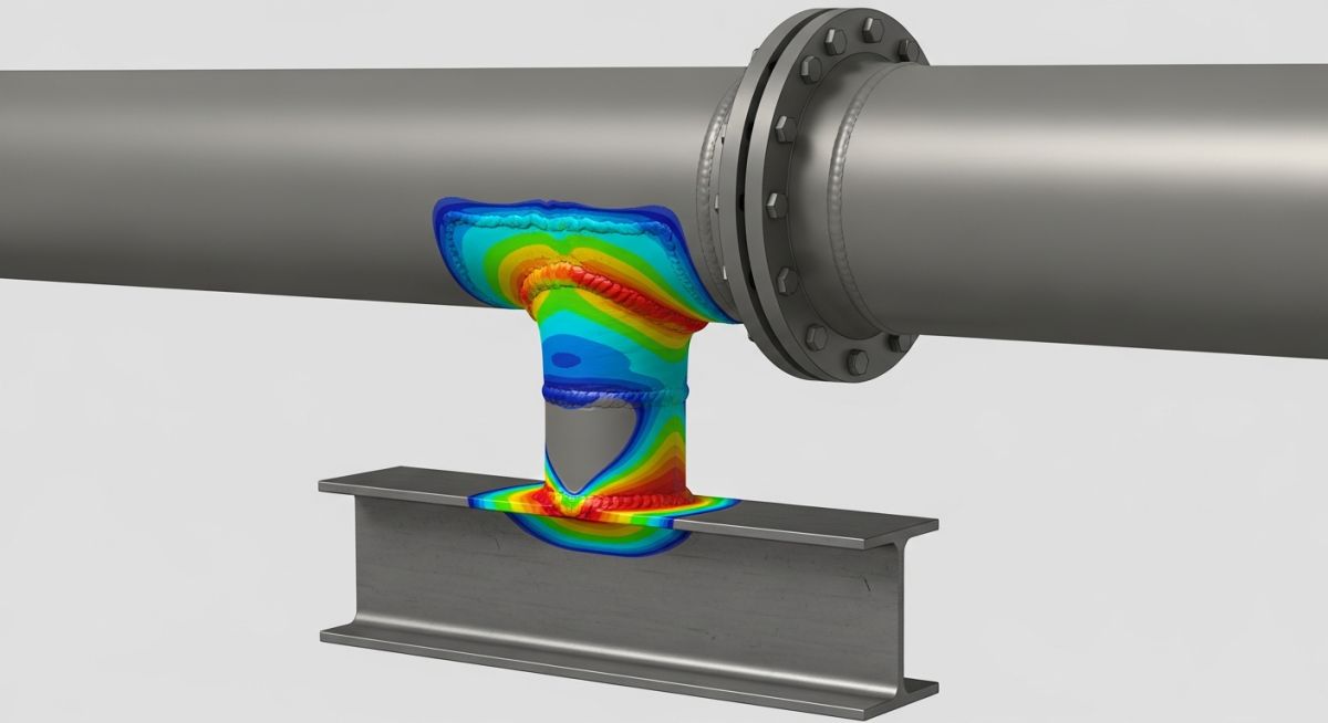
In my 20 years of piping engineering experience, I have seen many young engineers treat dummy supports as simple structural steel extensions. This is a dangerous mistake. A pipe trunnion, or dummy support, is welded directly to the run pipe wall. This direct attachment means that every kilonewton of thermal thrust, deadweight, and wind load is transferred directly into the thin shell of your process piping. Without a rigorous stress check, you risk localized wall buckling, plastic deformation, or pinhole leaks at the weld toe.
When I review stress packages for high-temperature steam lines or heavy crude headers, the trunnion junction is always a focal point. We must balance structural stiffness with local flexibility. If the support is too rigid, it overstresses the pipe wall; if it is too weak, it buckles. This guide walks you through the exact analytical steps, code requirements, and practical field realities of designing safe, reliable pipe trunnions.
Key Engineering Takeaways
- Understand the structural difference between a load-bearing trunnion and a non-structural dummy guide.
- Learn when to transition from simplified Kellogg calculations to advanced finite element analysis.
- Identify the geometric limits of WRC 107 and WRC 297 to avoid invalid stress results.
- Determine the exact thickness and width requirements for reinforcing pads on thin-walled run pipes.
- Establish a robust field verification workflow to ensure fabrication matches your stress model.
How to Run Pipe Trunnion Stress Calculation
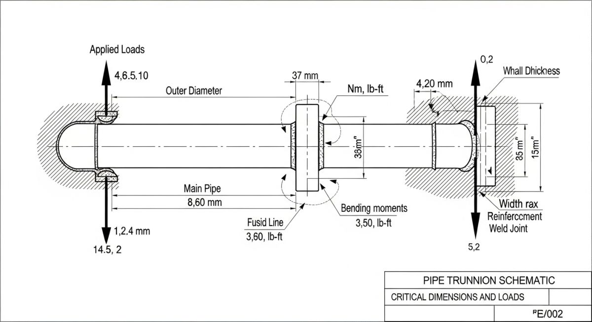
To perform an accurate stress check, we must first identify all forces and moments acting on the trunnion. These loads are typically extracted from global piping stress analysis software like CAESAR II. The forces acting at the junction are categorized into three orthogonal axes: axial force, radial force, in-plane bending moment, out-of-plane bending moment, and torsional moment.
In my practice, I utilize three primary methods depending on the complexity and criticality of the piping system:
- Kellogg’s Method: A classical, conservative hand-calculation technique suitable for standard pipe sizes and moderate temperatures. It simplifies the geometry by treating the trunnion as a hollow circular beam welded to a cylindrical shell.
- WRC 107 / WRC 297 Bulletins: Semi-analytical methods based on shell theory. They are highly accurate but have strict geometric limits regarding the ratio of the trunnion diameter to the run pipe diameter.
- Finite Element Analysis (FEA): The gold standard for critical, high-temperature, or thin-walled piping where analytical methods fall outside their validity limits.
Step-by-Step Analytical Calculation Workflow
Let us look at the mathematical framework behind the localized stress evaluation. First, we calculate the nominal longitudinal stress in the run pipe due to internal pressure:
Where:
P = Internal design pressure (MPa)
D_outer = Outside diameter of the run pipe (mm)
t_run = Nominal wall thickness of the run pipe minus corrosion allowance (mm)
Next, we calculate the localized bending stress caused by the external moments transferred through the trunnion. The local bending stress on the run pipe wall is given by:
Where:
C_local = Local stress concentration factor derived from WRC 107 curves or Kellogg coefficients
M_combined = Vectorial sum of in-plane and out-of-plane bending moments (N-mm)
Z_run_local = Section modulus of the run pipe wall interface (mm³)
The total combined stress (Stress Intensity) at the junction must satisfy the allowable limits defined by ASME B31.3. For sustained loads (weight + pressure), the combined stress must not exceed the basic allowable stress (S_h) of the run pipe material at design temperature. For expansion loads (thermal displacement), the stress range must remain within the allowable displacement stress range (S_A).
Reinforcing Pad (Re-pad) Design Rules
When the local stress exceeds the allowable limit, the most cost-effective solution is to add a reinforcing pad (re-pad). The re-pad increases the effective wall thickness of the run pipe at the junction, distributing the local loads over a larger surface area. In my experience, the re-pad thickness should match the run pipe thickness, and its outer diameter should be at least 1.5 times the trunnion outer diameter. Always ensure a vent hole (typically 1/4 inch NPT) is drilled in the re-pad to prevent pressure buildup during welding and to serve as a weep hole for leak detection during service.
Why Pipe Trunnion Stress Calculation Prevents Failures
The table below outlines the standard recommended dummy support sizes based on the run pipe nominal diameter. These dimensions serve as an initial engineering estimate before running formal stress verification.
| Run Pipe Size (NPS) | Recommended Dummy Size (NPS) | Minimum Dummy Schedule | Max Allowable Length (mm) | Re-pad Requirement Trigger |
|---|---|---|---|---|
| 3″ to 4″ | 2″ | Sch 80 | 450 | Run pipe Sch < Std |
| 6″ to 8″ | 4″ | Sch 40 | 600 | Run pipe Sch < Std |
| 10″ to 12″ | 6″ | Sch 40 | 750 | D/t ratio > 60 |
| 14″ to 18″ | 8″ | Sch 40 | 900 | D/t ratio > 50 |
| 20″ to 24″ | 10″ | Sch XS | 1000 | Mandatory for all cases |
Technical Mapping & Specifications Matrix
To ensure seamless integration between stress analysts and structural designers, the following matrix maps the core technical entities, design parameters, and their governing code references.
| Design Entity | Acronym | Primary Physical Parameter | Governing Code / Standard |
|---|---|---|---|
| Welding Research Council | WRC | Local Shell Stress Coefficients | WRC Bulletin 107 / 297 |
| Process Piping Code | ASME B31.3 | Allowable Stress Limits (S_h, S_A) | ASME B31.3 Chapter II |
| Pressure Vessel Code | ASME BPVC | Alternative Local Stress Evaluation | ASME Sec VIII Div 2 |
| Finite Element Analysis | FEA | Mesh-based Stress Intensity Mapping | ASME BPVC Annex 5.F |
Site Verification Checklist for Trunnion Installation
In my years of field auditing, I have frequently discovered that field welders cut dummy supports shorter or longer than specified to fit structural steel variations. This alters the moment arm and invalidates the stress calculation. Use this checklist to verify compliance before line commissioning.
Trunnion Quality Control Checkpoints
-
Dimensional Verification: Measure the exact length of the fabricated dummy support. Verify that the length matches the CAESAR II model input within a tolerance of +/- 10mm.
-
Material Grade Match: Confirm that the dummy support pipe material is compatible with the run pipe material to prevent galvanic corrosion and differential thermal expansion.
-
Reinforcing Pad Vent Hole: Verify that a 1/4″ NPT vent hole is drilled in the reinforcing pad and left unplugged or packed with heavy grease to prevent moisture ingress.
-
Welding Profile: Inspect the fillet weld size at the trunnion-to-run pipe (or re-pad) junction. The weld throat must meet the minimum requirements of ASME B31.3 Paragraph 328.5.4.
-
Non-Destructive Testing (NDT): Ensure Dye Penetrant (DP) or Magnetic Particle Testing (MPT) is performed on the root and final weld passes to check for surface cracks.
-
Support Clearance: Check that the end of the dummy support has adequate clearance to slide on the structural steel shoe or beam without binding during thermal expansion.
-
Drain Hole Presence: For vertically oriented dummy supports, ensure a drain hole is drilled at the lowest point of the dummy pipe to prevent water accumulation and internal corrosion.
Field Case Study: Real-World Application
This case highlights why relying on “rules of thumb” for high-temperature piping is a recipe for disaster. A simple, proactive stress check during the detail engineering phase would have saved the plant three days of unscheduled shutdown and thousands of dollars in emergency weld repairs.
Frequently Asked Engineering Questions
What is the difference between a pipe trunnion and a dummy support?
When is a reinforcing pad (re-pad) required for a pipe trunnion?
Why does WRC 107/297 have limitations for pipe trunnion stress calculation?
How do you model a pipe trunnion in CAESAR II?
What are the typical allowable stress limits for dummy supports under ASME B31.3?
Can a pipe trunnion be used on insulated piping systems?
===FAQ_BLOCK===
Complete Course on
Piping Engineering
Check Now
Key Features
- 125+ Hours Content
- 500+ Recorded Lectures
- 20+ Years Exp.
- Lifetime Access
Coverage
- Codes & Standards
- Layouts & Design
- Material Eng.
- Stress Analysis


