Table of Contents
Ultimate Engineering Guide to API 6D Valve Design and Testing
In my 20 years of specifying pipeline valves for major midstream projects, I have seen how a minor misunderstanding of valve standards can lead to catastrophic field failures. Many young engineers mistake a standard process valve designed under ASME B16.34 for a dedicated pipeline valve. When you are dealing with cross-country pipelines carrying volatile hydrocarbons, you must design and test according to the rigorous mandates of API 6D.
This guide draws directly from my field experience troubleshooting pipeline manifolds, pig launcher stations, and terminal facilities. We will dissect the exact mechanical differences, design calculations, and testing protocols that make the API 6D valve the undisputed benchmark for pipeline integrity.
- The critical design differences between DBB, DIB-1, and DIB-2 seat configurations.
- How to calculate thermal cavity pressure rise in liquid-filled valve bodies.
- The exact hydrostatic shell and seat test durations required for field acceptance.
- A real-world case study of a thermal overpressure blowout and how we solved it.
Complete Course on
Piping Engineering
Check Now
Key Features
- 125+ Hours Content
- 500+ Recorded Lectures
- 20+ Years Exp.
- Lifetime Access
Coverage
- Codes & Standards
- Layouts & Design
- Material Eng.
- Stress Analysis
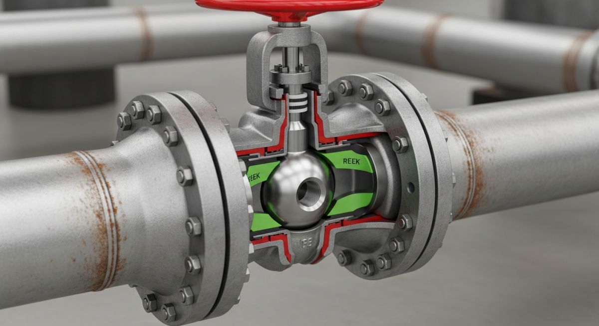
When I review pipeline datasheets, the first thing I look for is the seat configuration. Unlike standard process valves, an API 6D valve must handle the unique challenges of pipeline operations, including pigging, thermal expansion of trapped fluids, and double isolation.
Understanding DBB vs. DIB Configurations
The terminology surrounding Double Block and Bleed (DBB) and Double Isolation and Bleed (DIB) is a frequent source of confusion. Let us clarify these definitions based on the official API 6D standard:
- Double Block and Bleed (DBB): A single valve with two seating surfaces that, in the closed position, provides a seal against pressure from both ends of the valve with a means of venting or bleeding the cavity between the seating surfaces. If the upstream seat leaks, the pressure bypasses the downstream seat if the cavity is open to the bleed.
- Double Isolation and Bleed (DIB-1): A single valve with two seating surfaces, each of which, in the closed position, provides a seal against pressure from a single source, with a means of venting/bleeding the cavity. Both seats are bi-directional (Double Piston Effect or DPE). If one seat fails, the second seat still isolates the pipeline.
- Double Isolation and Bleed (DIB-2): A single valve with one bi-directional seat (DPE) and one uni-directional seat (Self-Relieving or SPE). This provides redundant isolation from one direction while allowing automatic cavity relief in the other.
Never specify a DIB-1 (double bi-directional seat) valve in liquid service without an external thermal relief valve. Because both seats seal from both sides, liquid trapped in the body cavity cannot escape. When solar radiation heats the valve body, the pressure rise can easily rupture the valve casing.
Calculating Thermal Cavity Pressure Rise
To understand why cavity relief is mandatory, let us look at the physics of trapped liquids. The pressure rise ($\Delta P$) due to a temperature increase ($\Delta T$) in a completely filled, rigid cavity is calculated using the volumetric thermal expansion coefficient ($\beta$) and the isothermal compressibility ($\chi$) of the fluid:
Let us plug in real-world numbers for water trapped inside a closed valve cavity at 20°C:
- • Volumetric expansion coefficient of water (β): 2.07 x 10⁻⁴ /°C
- • Isothermal compressibility of water (χ): 4.5 x 10⁻⁵ /bar
This means that for every 1°C rise in temperature, the pressure inside the trapped cavity increases by approximately 4.6 bar (66.7 psi). If a pipeline manifold shuts down on a cool morning at 15°C and the sun heats the valve body to 35°C by afternoon (ΔT = 20°C), the cavity pressure will spike by 92 bar (1,334 psi) above the operating pressure! This will easily exceed the limits of a Class 150 or Class 300 valve, leading to seal blowout or body deformation.
During Factory Acceptance Testing (FAT), I always verify that the manufacturer holds the test pressures for the full duration specified by the standard. The table below outlines the minimum hydrostatic test durations required for API 6D valves.
| Valve Size (NPS) | Shell Test Pressure | Shell Duration (Minutes) | Seat Test Pressure | Seat Duration (Minutes) |
|---|---|---|---|---|
| ≤ 2 | 1.5 x Rating | 2 | 1.1 x Rating | 2 |
| 2.5 to 6 | 1.5 x Rating | 5 | 1.1 x Rating | 5 |
| 8 to 10 | 1.5 x Rating | 15 | 1.1 x Rating | 5 |
| 12 to 18 | 1.5 x Rating | 30 | 1.1 x Rating | 5 |
| ≥ 20 | 1.5 x Rating | 30 | 1.1 x Rating | 10 |
To assist design engineers in mapping technical parameters to industry standards, I have compiled this cross-reference matrix linking physical requirements to their governing codes.
| Entity Name | Acronym | Physical Parameter / Requirement | Reference Standard |
|---|---|---|---|
| Double Block and Bleed | DBB | Simultaneous upstream and downstream isolation with cavity vent | API 6D Section 3.1.10 |
| Double Isolation and Bleed | DIB-1 | Two bi-directional sealing seats requiring external cavity relief | API 6D Section 3.1.11 |
| Maximum Allowable Working Pressure | MAWP | Pressure rating based on material group and design temperature | ASME B16.34 Table 2 |
| Cavity Relief Pressure | CRP | Relief mechanism must activate at less than 1.33 times valve rating | API 6D Section 5.8 |
| Minimum Wall Thickness | t_min | Minimum structural thickness to withstand hoop stress and external loads | ASME B16.34 / API 6D |
When a shipment of valves arrives at the construction site, you cannot afford to take the manufacturer’s word for granted. I have established a strict field verification checklist that my inspection teams use on every project.
-
Nameplate Verification: Confirm the API 6D monogram is stamped, along with the correct nominal size, pressure class, body material, and unique serial number.
-
Mill Test Certificate (MTC) Review: Cross-reference the heat numbers stamped on the valve body and bonnet with the MTCs to verify chemical composition and mechanical properties.
-
Flange Face Inspection: Check the flange surface finish (serrated spiral or concentric) to ensure it complies with ASME B16.5 requirements (typically 125 to 250 AARH).
-
Cavity Relief Verification: For liquid service valves, verify that the self-relieving seats (SPE) or external bypass relief valves are correctly installed and oriented.
-
NACE MR0175 Compliance: If the service is sour, verify that the valve materials comply with NACE MR0175/ISO 15156 for hardness limits (typically ≤ 22 HRC for carbon steel).
Field Case Study: Real-World Application
During a hot summer shutdown at a crude oil terminal in the Middle East, a 24-inch Class 600 trunnion-mounted ball valve failed catastrophically. The valve was specified with a DIB-1 (double bi-directional seat) configuration to ensure absolute isolation. However, the design team forgot to specify an external thermal relief valve. When the pipeline was isolated, crude oil was trapped inside the valve body cavity. Solar radiation heated the valve body from 25°C to 48°C. The resulting thermal expansion caused the cavity pressure to spike to 165 bar, blowing out the body-to-bonnet gasket and spilling 40 barrels of crude oil.
I was brought in to lead the root cause analysis. We calculated that the 23°C temperature rise generated over 105 bar of additional pressure, exceeding the Class 600 design limit of 102.1 bar. We replaced the damaged valve with an API 6D compliant ball valve configured with a DIB-2 seat arrangement (one bi-directional seat and one self-relieving seat). This allowed the valve to maintain absolute isolation from the upstream side while automatically relieving any cavity overpressure to the downstream pipeline. Since this modification, the terminal has operated for five years without a single cavity overpressure incident.
My direct recommendation for any liquid pipeline project is to mandate self-relieving seats (SPE) on at least one side of the valve, or to install a dedicated, piped thermal relief system. Never rely on manual venting for thermal expansion protection.
Frequently Asked Engineering Questions
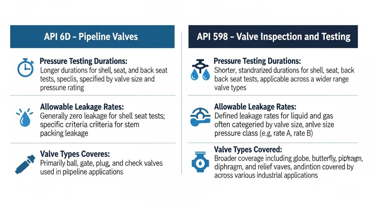
What is the primary difference between API 6D and ASME B16.34?
When should I specify a DIB-1 valve instead of a DBB valve?
Why is cavity relief mandatory for liquid service valves?
Can an API 6D valve be used in gas service?
What is the difference between SPE and DPE seats?
How does API 6D handle fire testing?

📚 Recommended Resources: API 6D valve
Read these Guides
🎓 Advanced Training


Related posts:
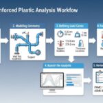
![Infographic flowchart of the GRP GRE FRP piping stress analysis workflow in START-PROF.]()
Rigid Struts: Definition, Applications, and Modeling in Caesar II
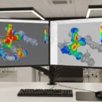
![3D stress analysis model of GRP piping system in START-PROF software showing stress distribution.]()
Stress Analysis of GRP / GRE / FRP Piping using START-PROF
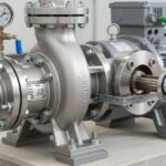
![Industrial centrifugal pump installed on a concrete foundation with precision piping and alignment.]()
How to Use a Pump Installation Checklist for Maximum Reliability
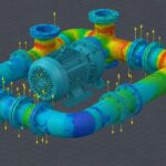
![3D Caesar II pipe stress analysis model of a centrifugal pump piping system showing stress distribution.]()
Pump-Piping Alignment Caesar II Stress Analysis Methodology
![3D render of a structural steel cross-bracing connection with a gusset plate.]()
Mastering Steel Connections with a Cross-Bracing Design Example
![Industrial engineer checking shaft alignment on a centrifugal pump during commissioning.]()
How to Use a Pump Commissioning Checklist for Start-Up