What is a Pipe Anchor? Comprehensive Engineering Guide to Design, Types, and Functions

I will never forget a midnight call I received during a plant expansion project back in 2018. A massive high-pressure steam line had literally ripped its structural guide clean off the I-beam, buckling the pipeline like a cheap plastic straw. The culprit? The design team had placed a rigid pipe anchor right where the system needed absolute freedom to breathe and expand thermally. In my experience on the field, mistakes involving a pipe anchor are rarely quiet; they manifest as catastrophic flange leaks, destroyed pump nozzles, or structural failures. If you miscalculate how your system is anchored, the laws of thermodynamics will rewrite your design by force.
Executive Engineering Takeaways
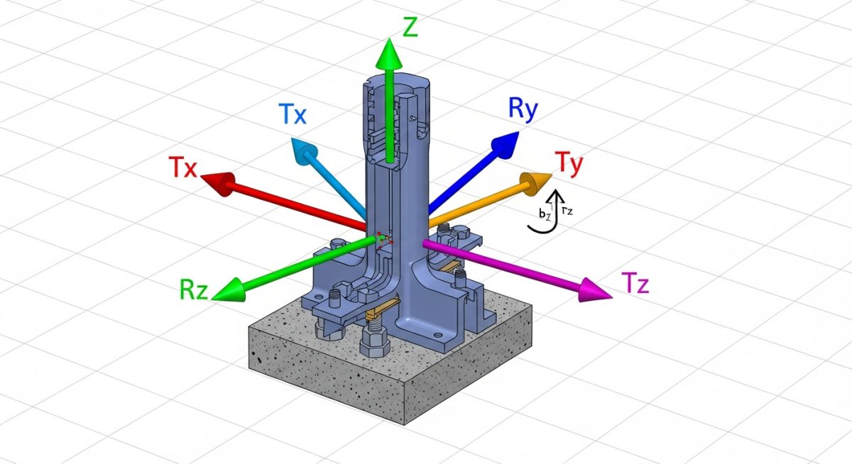
- Complete Restraint: A standard fixed pipe anchor completely eliminates all 6 degrees of structural freedom to partition thermal movement.
- ASME Compliance: Code requirements under ASME B31.3 mandate exact structural design calculations to prevent localized stress concentration at anchor welds.
- Strategic Placement: Proper positioning splits large piping networks into manageable expanding segments, directly shielding highly sensitive rotating equipment.
What is a Pipe Anchor? Quick Definition
A pipe anchor is a rigid structural piping support designed to completely restrict structural movement in all three translational (X, Y, Z) and all three rotational axes. It acts as a fixed point that splits a piping system into independent thermal expansion loops, preventing destructive stresses from reaching connected equipment.
Guide Roadmap
Interactive SGE Flashcards: Pipe Anchor Design Check
Hover over or tap a card to reveal the engineering standard and field-tested pro-tip.
What exactly happens to the six degrees of freedom when you install a rigid pipe anchor?
Hover to Flip →All six degrees of freedom are fully locked, completely eliminating translational and rotational movements at that node.
Reference: Core Piping Mechanics
Atul’s Pro-Tip: Ensure the supporting structural steel can actually absorb the massive resulting load transfer.
How does a directional pipe anchor function differently from a fully fixed pipe anchor?
Hover to Flip →It restricts movements in specific directions while allowing absolute freedom along one designated axial or lateral vector.
Reference: Support Design Criteria
Atul’s Pro-Tip: I use these frequently on piperacks to guide expanding pipe directly into structural loops.
Which specific section of the ASME B31.3 code governs the structural design requirements for a pipe anchor?
Hover to Flip →Paragraph 321 governs the structural integrity rules for piping supports, anchors, and attachments.
Reference: ASME B31.3 Para 321
Atul’s Pro-Tip: Always double-check dynamic friction factors when evaluating anchor loads on civil columns.
Why must you never install a completely rigid pipe anchor directly on a highly sensitive pump nozzle connection?
Hover to Flip →The massive thermal loads will warp the pump casing and ruin alignment, tearing up internal bearings rapidly.
Reference: API 610 Nozzle Load Limits
Atul’s Pro-Tip: Isolate the pump nozzle entirely using well-spaced expansion loops or flexible joint systems.
Where should you logically position a pipe anchor when designing a large, complex thermal expansion loop?
Hover to Flip →Place anchors at both outer ends of the straight run to force thermal expansion movements into the loop legs.
Reference: Loop Geometry Rules
Atul’s Pro-Tip: Ensure structural anchor welds are continuous; intermittent pass welding fails here.
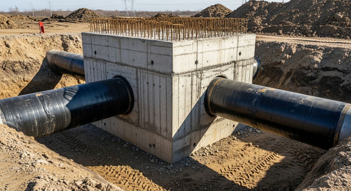
What structural role does a concrete thrust block play when used as a buried pipe anchor system?
Hover to Flip →It transmits high directional thrust forces safely into solid surrounding soil, securing high-pressure bends.
Reference: AWWA M11 Design Standards
Atul’s Pro-Tip: Always verify the soil bearing capacity under wet conditions before pouring concrete.
How do you protect thin-walled stainless steel process pipelines from severe localized stress at a heavy pipe anchor?
Hover to Flip →You weld an engineered reinforcing wrapper pad directly to the pipe skin prior to setting structural anchor lugs.
Reference: Localized Wall Stresses
Atul’s Pro-Tip: Match the pad plate material chemistry perfectly to the line to eliminate galvanic wear.
What specific operational issue occurs if an insulation shoe on a hot process line binds against a directional pipe anchor guide?
Hover to Flip →The guide unintentionally locks up, behaving like a rigid fixed anchor and provoking massive line buckling.
Reference: Support Clearances
Atul’s Pro-Tip: Instruct field crews to clear out welding slag and carefully verify actual expansion gaps.
What is the mechanical purpose of utilizing an asymmetric directional pipe anchor layout on a piperack?
Hover to Flip →It balances unequal thermal expansion stresses occurring between heavily distinct process piping system branches.
Reference: Advanced Rack Routing
Atul’s Pro-Tip: Define these asymmetric boundary conditions early during your CAESAR II modeling phase.
How does extreme cryogenic thermal contraction impact the material selection process for a structural pipe anchor?
Hover to Flip →It necessitates low-temperature carbon steel or premium stainless alloys to prevent instant brittle fracture failures.
Reference: Cryogenic Support Spec
Atul’s Pro-Tip: Standard commercial structural steel plate will fracture cleanly under cold cryogenic thermal shock.
What critical calculation must a pipe stress engineer perform regarding the anchor structural steel baseplate design?
Hover to Flip →You must evaluate the exact bending moments and severe pull-out loads acting directly on foundation anchor bolts.
Reference: Baseplate Calculations
Atul’s Pro-Tip: Always implement a minimum 1.5 structural design safety factor on all concrete embeds.
How does intense water hammer fluid transience alter the design forces expected on a mainline pipe anchor?
Hover to Flip →It forces massive, instantaneous dynamic shock waves that far eclipse baseline static thermal calculations.
Reference: Fluid Transient Impacts
Atul’s Pro-Tip: Size these specialized anchors against peak transient surge pressures, not nominal operating metrics.
Piping Design Check: Pipe Anchor Mechanics
Test your field engineering intuition. Real-time feedback powered entirely by structural CSS code.
What is a Pipe Anchor? Definition and Core Principles
In my 15 years on the field managing hydrocarbon process networks, I have noticed that junior designers often confuse structural guides with a true, fully zero-tolerance pipe anchor. Let me clarify this distinct operational difference immediately. A basic guide template simply keeps a process line centered along its intended run path, allowing axial slide. A genuine pipe anchor, by absolute contrast, is an immovable structural boundary that locks every millimeter of movement down hard.
When you weld a pipe shoe solidly to the embedded steel on a massive piperack girder, you are engineering a fixed structural point. By introducing a rigid anchor, you purposefully separate your piping grid into isolated thermal zones. This deliberate mechanical division ensures that high stresses occurring in Zone A do not bleed down the line to blow out flanges or shatter fragile valve manifolds in Zone B.
CRITICAL FIELD WARNING: If your stress software model shows an anchor but your construction contractor builds a loose guide, you will buckle the pipe run under peak operating temperature.
Primary Functions of a Pipe Anchor in Piping Systems
But here is the catch that many engineers overlook: an anchor does not just sit there looking heavy. It continuously absorbs a massive cocktail of overlapping forces. In the field, we rely on a heavy-duty pipe anchor to perform three primary duties simultaneously:
- Absorbing Extreme Axial Thrust Loads: When internal system pressure surges or a massive column of fluid hits an elbow, severe pressure thrust forces try to tear the line apart. The anchor takes this dynamic hit full-on, transferring it down to the civil foundations.
- Isolating High-Value Rotating Machinery: Large pumps and high-pressure compressors have incredibly strict, razor-thin external load limits defined by API Standards. Placing an anchor strategically right before the equipment inlet acts as a solid shield, locking away incoming pipeline stress.
- Controlling Thermal Expansion Expansion Loops: Pipelines grow when hit with high-temperature process fluids. By anchoring specific coordinates, we physically force that expanding steel to deflect into our engineered expansion loops instead of spreading wildly through the facility.

Complete Course on Piping Engineering by Atul Singla on EPCLAND
Skip the guesswork and master real-world industrial plant design. Learn directly from my field project logs, featuring step-by-step CAESAR II modeling tutorials, ASME B31.3 compliance secrets, and full pipe support calculation workbooks.
Mechanical Types of Pipe Anchors
In the engineering field, we do not treat every anchor placement with the same brutal rigidity. Depending on what our flexibility analysis dictates in software like CAESAR II, we selectively deploy different mechanical families of supports to maintain systemic equilibrium under stress.
Fixed Pipe Anchors
This is your zero-compromise solution. A fixed pipe anchor mechanically structuralizes a hard barrier that prevents all linear translations and rotational twisting moments. In my experience on the field, these are typically constructed by welding heavy structural steel lugs, trunnions, or heavy-duty stanchions directly onto the pipe wall, which are then bolted or securely field-welded straight to the main structural steel grid or concrete foundations.
Directional Pipe Anchors
But here is the catch: sometimes, complete absolute rigidity is exactly what breaks your pipeline. That is why we utilize a directional pipe anchor. This mechanical support restricts movements along specific vectors while allowing free, uninhibited travel along another axis. For example, a directional anchor might lock down lateral displacement and axial rotation completely, but allow the pipe line to freely expand along its native longitudinal run direction.
Engineering Rules for Locating Pipe Anchors
In the field, we actually do this differently than what basic theoretical textbooks might lead you to believe. You cannot just scatter an anchor wherever you find a convenient structural column. I adhere to several strict engineering layout placement protocols to guarantee systemic code safety under ASME Standards:
- Always place an anchor at pipeline branch intersections: This completely decouples the heavy thermal displacement forces of the main run header from overstressing the smaller, thinner branch line tie-ins.
- Position anchors at both extreme outer ends of a straight piping run containing an expansion joint: If you omit this layout choice, the high internal pressure will instantly telescope the joint open to its maximum mechanical limit, pulling the pipe straight out of its hangers.
- Isolate complex thermal loops: Place anchors symmetrically on the main straight runs feeding into an expansion loop block to force all growing steel straight into the loop flex legs.
Critical Factors Affecting Pipe Anchor Design and Installation
When you step up to design a structural anchor, you must balance mechanical clearances with code compliance constraints. The table below details exactly how different design factors alter your structural approach:
| Design Factor | Fixed Anchor Strategy | Directional Anchor Strategy | ASME / API Standard Reference |
|---|---|---|---|
| Thermal Expansion Loads | Locks and absorbs full thermal thrust vectors. | Channels expansion into specific flexible loop paths. | ASME B31.3 Para 319 |
| Friction Coefficients | Zero translational slip occurs at the node. | Calculates steel-on-steel or PTFE pad sliding slip. | ASME B31.3 Para 321.1 |
| Equipment Isolation | Completely terminates forces before nozzles. | Allows safe unidirectional thermal growth away from casing. | API 610 / API 617 Nozzle Limits |
Engineering Estimator: Thermal Force at Fixed Anchor
Quick design check tool to approximate the raw axial force generated against a rigid fixed pipe anchor using carbon steel characteristics.
*Based on carbon steel modulus of elasticity E = 29×106 psi and thermal coefficient α = 6.5×10⁻⁶ in/in/°F. Formula used: Force = A × E × α × ΔT. Always verify complex arrangements within dedicated finite element software.
Case Study: Correcting a Failing High-Pressure Steam Header Pipe Anchor Layout
When I was working on a massive coastal refinery modification project, we encountered an operational nightmare during the pre-commissioning steam blow phase. A critical 24-inch high-pressure superheated steam header was generating severe, unexpected lateral deflection. The massive displacement began warping the structural steel cross-members on the primary piperack. Our initial look at the field configuration revealed that the original construction vendor had installed an incredibly rigid, fully fixed structural clamp down as the line's primary pipe anchor.
But here is the catch: that massive fixed anchor was forcing all 6 structural degrees of freedom to lock completely down at a coordinate where the line desperately needed to move. Because the pipeline could not expand naturally along its longitudinal running path, the internal thermal force accumulated rapidly until the header began buckling sideways. The stress concentrations at the base plate welds were climbing dangerously close to the maximum yield limits allowed under ASME B31.3 rules, risking a catastrophic structural tear.
In the field, we actually do this differently when a rigid layout compromises structural safety. I stepped in and immediately ordered the field crew to cut out the rigid welded assembly. We replaced it with a heavy-duty asymmetric directional pipe anchor configuration. This new structural support modification completely locked down lateral translation and torsional rotation to protect the close-by equipment headers, but left the axial running pathway entirely free to slip longitudinally.
This field engineering modification completely resolved the structural overstress issue. When the next hot steam cycle hammered the process network, the pipeline expanded precisely along its longitudinal axis, guiding the growth safely straight into the terminal expansion loop legs. The local displacement vanished entirely, and our post-incident stress analysis models showed a massive 65 percent drop in stress loads across all neighboring equipment nozzles.

About The Author: Atul Singla
Founder of EPCLAND & Senior Piping Design Consultant
I am a veteran industrial piping engineer dedicated to sharing hard field realities and technical code execution strategies. In my experience on the field, managing stress networks across complex refinery assets requires combining strict ASME standards with absolute practical simplicity. I design assets to perform under peak load, not just look beautiful on an office monitor.
Join the Global EPCLAND Network
Connect with real-time oil and gas engineering hubs, job boards, and advanced design insight forums.
Official Authorities & Engineering Standards
- • Verify official piping code criteria and compliance guidelines via the American Society of Mechanical Engineers (ASME) main standards portal.
- • Check industry structural equipment nozzle safe load limitations and machinery protections through the American Petroleum Institute (API) publication database.
- • Evaluate global structural testing, metallic tolerances, and validation methodologies via the International Organization for Standardization (ISO) technical platform.
Frequently Asked Questions About Pipe Anchors
Direct engineering answers to critical field inquiries regarding piping anchor design, mechanics, and installation.
What is the absolute difference between a pipe anchor and a standard pipe guide? ↓
Where are pipe anchors ideally positioned within an industrial processing facility? ↓
Which industrial engineering standards regulate the stress checking of a pipe anchor? ↓
How does an accidental or unintended anchor occur during construction? ↓
Why do thin-walled process lines require reinforcing plates at anchor coordinates? ↓
What is a directional pipe anchor and when do you deploy one? ↓
📚 Recommended Resources: Pipe Anchor
Read these Guides
- 📄 Thrust and Anchor Blocks in Pipelines: Design & Calculation Guide (2026)
- 📄 Ultimate Guide to U-Bolt Pipe Support: Types, ASME Installation, and Field Applications
- 📄 Spiral Welded Pipes: Applications, Manufacturing, and 2026 Standards
- 📄 Pipe Cold Cutting: The Engineering Guide to Sparkless Machining (2026)
🎓 Advanced Training


Related posts:
![Outdoor pipeline block valve station with large isolation valves and actuators.]()
What are Pipeline Block Valves and How to Design Stations
![3D CAD model of an industrial process plant showing equipment clearances and access platforms.]()
A Guide to Plant Clearances and Access Requirements
![Engineering technical bid evaluation spreadsheet comparing vendor specifications and compliance metrics.]()
How to Master Technical Bid Evaluation for Complex Engineering Procurement
![Large-diameter steel pipes with protective blue anti-corrosive epoxy coating stacked in an industrial facility.]()
Protecting Steel Pipes with Anti-Corrosive Steel Pipe Coatings
![3D CAD model of industrial piping showing stress intensification factor heatmaps at elbows and tees.]()
Why Stress Intensification Factor in Piping Dictates Fatigue Life
![A collection of different industrial pipe flange gaskets on a workbench]()
How to Select the Best Pipe Flange Gaskets for Piping Systems