Dye Penetration Test Guide for Piping and Weld Inspection
In my 20 plus years of managing piping integrity on high-pressure steam lines and chemical process plants, I have seen minor surface cracks escalate into catastrophic field failures. Visual inspection alone is never enough. When dealing with non-magnetic alloys like austenitic stainless steel, duplex steel, or nickel alloys, magnetic particle testing is out of the question. That is where the dye penetration test becomes my primary line of defense. It is a simple, highly effective, and field-proven method to expose micro-cracks, porosity, and cold laps before a system is pressurized.
Throughout my career, I have relied on this method to verify weld root passes and completed weldments. While the process seems straightforward, its success depends entirely on the technician’s attention to detail. A single skipped step or a rushed dwell time can easily mask a critical defect, leading to premature failure during service.
- The test only detects surface-breaking defects; subsurface discontinuities require volumetric methods like radiography or ultrasonic testing.
- Surface preparation is the most critical phase; any grease, rust, or paint will block the penetrant from entering the crack.
- Dwell times must be strictly controlled based on material type and ambient temperature.
- Fluorescent penetrants offer much higher sensitivity compared to visible red dyes under ambient light.
- Post-test cleaning is mandatory to prevent chemical corrosion, especially on stainless steel piping systems.
What is a Dye Penetration Test?
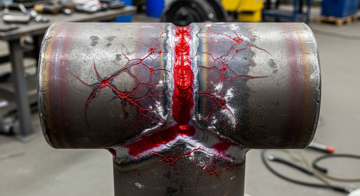
Liquid Penetrant Inspection: A highly sensitive surface inspection methodology designed to reveal surface-breaking discontinuities in metallic and non-metallic components. This non-destructive evaluation relies on capillary action to draw a liquid dye into surface openings, which are subsequently made visible using a developer agent under appropriate lighting conditions.
The fundamental physics of this test rely on capillary action, which is the ability of a liquid to flow into narrow spaces without the assistance of, or even in opposition to, external forces like gravity. The relationship governing this fluid movement is described by Washburn’s equation, which determines the penetration depth of a liquid into a capillary pore:
Where:
• gamma represents the surface tension of the penetrant fluid.
• r represents the capillary radius or crack width.
• theta represents the contact angle between the fluid and the crack wall.
• t represents the dwell time allowed for penetration.
• eta represents the dynamic viscosity of the penetrant fluid.
To maximize the sensitivity of the test, the penetrant must have a very low contact angle (close to zero degrees), meaning it has excellent wetting ability. It must also possess high surface tension and low viscosity to rapidly migrate into micro-cracks. In my experience, selecting a penetrant with the correct chemical balance is critical when inspecting high-alloy steels, as halogenated compounds can cause stress corrosion cracking over time.
How Does the Dye Penetration Test Work?
Capillary Action Testing: The physical process where low-viscosity liquid enters narrow surface-breaking cracks against gravity due to adhesive forces between the liquid and solid surface. This mechanism requires precise dwell times and meticulous surface preparation to ensure the penetrant fully occupies the defect volume before developer application.
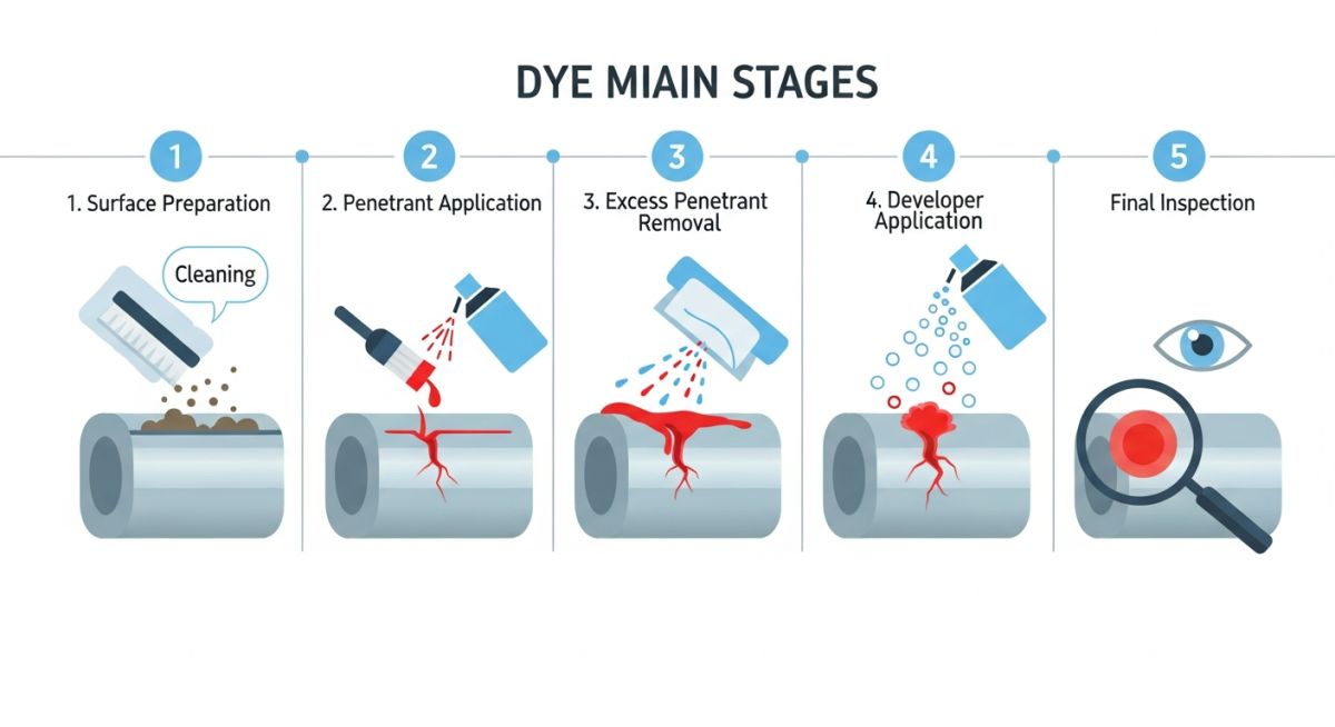
The entire testing sequence is a delicate balance of chemistry and timing. I have broken down the standard field procedure into seven distinct phases that must be executed sequentially without shortcutting:
- Initial Surface Preparation: The test surface must be completely free of oil, grease, rust, scale, paint, and weld spatter. I always insist on using high-quality solvent cleaners compliant with ASTM E165.
- Penetrant Application: The liquid penetrant is applied by spraying, brushing, or dipping. The entire area of interest must remain completely wet during the entire dwell period.
- Penetrant Dwell Time: The penetrant must be left on the surface for a specified duration to allow capillary action to take place. This typically ranges from 5 to 30 minutes depending on the material and expected defect type.
- Excess Penetrant Removal: This is the most sensitive step. The excess surface penetrant must be removed without washing the penetrant out of the cracks. For solvent-removable systems, use a clean, lint-free cloth moistened with solvent—never spray solvent directly onto the test surface.
- Developer Application: A thin, uniform layer of developer is applied. The developer acts as a blotter, drawing the trapped penetrant back out of the cracks to the surface, where it spreads and becomes visible.
- Developing and Inspection: The developer must be allowed to work for a minimum development time (usually half of the penetrant dwell time). Inspection is then conducted under adequate lighting (minimum 1000 lux for visible dye, or UV-A light of at least 1000 microwatts per square centimeter for fluorescent systems).
- Post-Test Cleaning: Once the inspection is complete and documented, the developer and penetrant residues must be thoroughly cleaned off to prevent future corrosion or interference with subsequent welding operations.
What Standards Govern Liquid Penetrant Testing?
NDT Inspection Standards: The regulatory frameworks established by international bodies to standardize penetrant materials, testing procedures, and acceptance criteria for industrial components. Compliance with these codes ensures consistency, safety, and reliability across global manufacturing and construction projects.
In my projects, I strictly enforce the dwell times specified by ASME Section V Article 6. The table below outlines the minimum dwell times required for various materials and product forms at temperatures between 50 degrees Fahrenheit and 125 degrees Fahrenheit.
| Material Type | Product Form | Type of Discontinuity | Penetrant Dwell (Min) | Developer Dwell (Min) |
|---|---|---|---|---|
| Aluminum, Copper, Brass | Welds, Castings | Cracks, Porosity, Laps | 5 minutes | 10 minutes |
| Stainless Steel, Nickel Alloys | Welds, Piping | Cracks, Lack of Fusion | 10 minutes | 10 minutes |
| Carbide-Tipped Tools | Brazed Joints | Lack of Bond, Cracks | 5 minutes | 10 minutes |
| Plastic Materials | Molded Parts | Cracks, Porosity | 5 minutes | 10 minutes |
| Glass, Ceramics | All Forms | Cracks, Thermal Shock | 5 minutes | 10 minutes |
To select the correct testing system for your specific application, you must understand the classifications defined by ASTM E165 and AMS 2644. The matrix below maps these systems to their typical industrial applications.
| System Parameter | Classification Type | Technical Description | Typical Application | Standard Reference |
|---|---|---|---|---|
| Penetrant Type | Type I | Fluorescent dye requiring UV-A light source | Aerospace, high-pressure gas piping | AMS 2644 / ASTM E1417 |
| Penetrant Type | Type II | Visible red dye visible under white light | General structural welds, field piping | ASME Sec V Art 6 / ASTM E165 |
| Removal Method | Method A | Water-washable penetrant containing emulsifiers | Rough castings, high-volume parts | ASTM E165 |
| Removal Method | Method C | Solvent-removable requiring manual wipe | Field weld inspection, localized repairs | ASME Sec V Art 6 |
| Developer Form | Form d | Non-aqueous wet developer (solvent-based spray) | High-sensitivity field inspections | AMS 2644 |
How to Perform Dye Penetration Testing?
Field Inspection Protocol: The systematic execution of surface preparation, chemical application, and visual assessment under controlled environmental conditions. Adhering to a structured field checklist ensures that no critical steps are bypassed, minimizing false positives and missed defects.
Before signing off on any weld inspection report, I run through this checklist on-site to verify that the testing was performed in strict compliance with ASME Section V.
Field Case Study: Real-World Application
During the pre-commissioning phase of a chemical processing plant, a 12-inch Schedule 40S Type 316L stainless steel piping system carrying highly corrosive nitric acid began weeping during the hydrostatic test at 450 psi. Visual inspection of the circumferential butt welds showed no obvious defects. The welding logs indicated that all parameters were within the welding procedure specification (WPS), but the weeping persisted at three distinct weld joints.
I was called to the site to investigate. I ordered an immediate dye penetration test using a Type II, Method C solvent-removable visible red dye system. After meticulous solvent cleaning and a 15-minute penetrant dwell time, we applied a non-aqueous wet developer. Within 3 minutes, distinct, continuous red linear indications appeared along the heat-affected zone (HAZ) of the welds.
The indications revealed intergranular stress corrosion cracking (IGSCC) caused by sensitization during welding. The welder had exceeded the maximum interpass temperature, allowing chromium carbides to precipitate at the grain boundaries.
Based on these findings, we gouged out the affected weld zones, re-welded the joints using strict interpass temperature controls (below 350 degrees Fahrenheit), and verified the root and final passes using the same dye penetration test protocol. The system successfully passed the subsequent hydrostatic test without any leakage. This case proved to the project team that visual inspection is completely inadequate for detecting micro-fissures in high-alloy piping.
What are the Advantages and Disadvantages?
Method Evaluation: The comparative analysis of liquid penetrant testing against other non-destructive testing methods to determine its suitability based on material type, cost, speed, and defect orientation. Understanding these trade-offs is key to selecting the most efficient inspection program.
Like any non-destructive testing method, the dye penetration test has distinct strengths and limitations that you must weigh during the engineering planning phase.
- Extremely high sensitivity to small, tight surface-breaking cracks.
- Applicable to a wide range of materials, including magnetic and non-magnetic metals, plastics, and ceramics.
- Highly portable and cost-effective; does not require heavy electrical equipment or radiation shielding.
- Provides immediate, easy-to-interpret visual indications directly on the part surface.
- Can inspect complex shapes and large surface areas rapidly in a single operation.
- Strictly limited to surface-breaking defects; cannot detect subsurface cracks or internal voids.
- Cannot be used on porous materials like concrete, wood, or highly porous sintered metals.
- Requires direct physical access to the surface being inspected.
- Extremely sensitive to surface cleanliness; contaminants can easily mask defects.
- Chemical residues can cause corrosion if post-cleaning is not performed thoroughly.
Frequently Asked Engineering Questions
What is the difference between Type I and Type II penetrants?
Why is surface preparation so critical in dye penetration testing?
Can dye penetration testing detect subsurface defects?
What is the minimum dwell time for a dye penetration test?
How does temperature affect the dye penetration test?
What are the main limitations of liquid penetrant testing?
===
Complete Course on
Piping Engineering
Check Now
Key Features
- 125+ Hours Content
- 500+ Recorded Lectures
- 20+ Years Exp.
- Lifetime Access
Coverage
- Codes & Standards
- Layouts & Design
- Material Eng.
- Stress Analysis