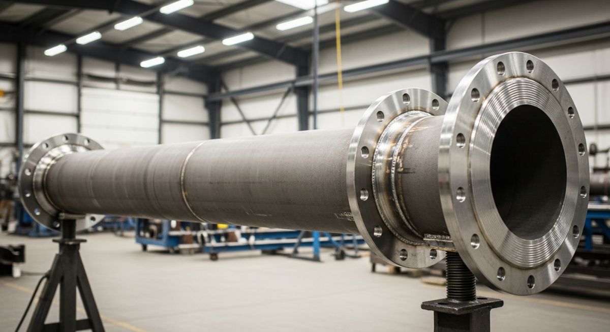
What is a Pipe Spool and Why is it Important in Piping?
In my 20 years of managing piping engineering projects, I have seen field construction schedules fall apart due to unpredictable weather, welder shortages, and tight site spaces. That is where the pipe spool becomes a lifesaver. Instead of welding every single joint high up on a pipe rack or in a muddy trench, we prefabricate these components in a highly controlled workshop. This approach shifts the bulk of the high-risk welding, non-destructive testing, and heat treatment to a shop floor where quality control is absolute.
When these pre-assembled units arrive at the construction site, they are ready to be bolted or welded together like a giant industrial puzzle. This method not only accelerates the project timeline but also drastically reduces field labor costs and safety hazards. Let us dive deep into the engineering, design, and fabrication standards that make these components the backbone of modern industrial construction.
Key Engineering Takeaways
- Controlled Quality: Shop fabrication ensures superior weld quality under stable environmental conditions, adhering strictly to ASME Section IX.
- Schedule Acceleration: Parallel fabrication in the shop while civil works progress on-site can compress project timelines by up to thirty percent.
- Cost Efficiency: Shifting labor from field rates to shop rates reduces overall piping installation costs significantly.
- Rigid Tolerances: Adherence to PFI ES-3 standards ensures that spools fit perfectly during field erection without requiring costly modifications.
What is a Pipe Spool in Modern Piping?
[Pipe Spool Fabrication]: The process of manufacturing pipe spools involves cutting, beveling, fitting, and welding raw piping components into pre-designed configurations within a certified fabrication shop. This controlled environment ensures strict adherence to ASME Section IX welding qualifications and non-destructive testing requirements before field delivery.
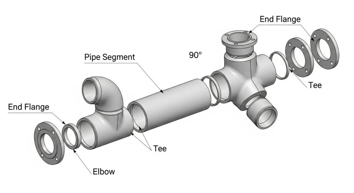
To understand why a pipe spool is so critical, we must look at how it is engineered. A typical spool consists of raw pipe cut to specific lengths, fitted with elbows, tees, reducers, and flanges. These components are welded together in a shop using highly automated processes like Gas Tungsten Arc Welding (GTAW) and Submerged Arc Welding (SAW).
In my experience, the design of these spools must account for shipping limitations, crane lifting capacities, and field weld locations (often called “field fit-up welds” or “golden welds”). We design these spools using advanced 3D modeling software like CADWorx or SmartPlant 3D, which automatically generates isometric drawings detailing every dimension, material grade, and weld number.
Calculating Pipe Wall Thickness Under ASME B31.3
Before any fabrication begins, the design engineer must verify that the pipe wall thickness is sufficient to withstand the internal design pressure. Under ASME B31.3 Process Piping Section 304.1.2, the minimum required wall thickness (t) is calculated using the following formula:
Where:
- P: Internal design gage pressure (psi or MPa)
- D: Outside diameter of the pipe (inches or mm)
- S: Allowable stress value for the material from Table A-1 (psi or MPa)
- E: Quality factor from Table A-1A or A-1B
- W: Weld joint strength reduction factor
- Y: Coefficient from Table 304.1.1 (typically 0.4 for ductile metals at temperatures below 900°F)
Let us walk through a practical engineering example. Suppose we are designing a carbon steel pipe spool using ASTM A106 Grade B pipe. The design parameters are:
- Outside Diameter (D) = 8.625 inches (NPS 8)
- Design Pressure (P) = 600 psi
- Design Temperature = 400°F
- Allowable Stress (S) = 20,000 psi (for ASTM A106 Gr. B at 400°F)
- Quality Factor (E) = 1.0 (Seamless pipe)
- Weld Factor (W) = 1.0
- Coefficient (Y) = 0.4
Plugging these values into our formula:
t = 5175 / (2 * (20000 + 240))
t = 5175 / 40480
t = 0.1278 inches (approx. 3.25 mm)
To find the nominal wall thickness, we must add a corrosion allowance (typically 0.125 inches or 3 mm) and account for the standard mill tolerance of 12.5 percent. This calculation ensures that the fabricated pipe spool will safely handle the process fluid without risk of mechanical failure.
Why the Pipe Spool is Critical for Projects
[Pipe Spool Optimization]: Utilizing prefabricated pipe spools reduces field labor hours, minimizes weather-related delays, and significantly lowers overall project costs by shifting up to eighty percent of piping fabrication to a controlled shop environment. This modular approach enhances safety, improves weld quality, and accelerates the construction schedule of complex industrial facilities.
In my years on site, I have observed that field welding is highly susceptible to environmental factors. Wind can disrupt shielding gas during GTAW welding, leading to porosity. Humidity and rain can introduce moisture, causing hydrogen cracking. By shifting these operations to a dedicated fabrication shop, we eliminate these variables entirely.
Furthermore, shop fabrication allows for the use of advanced positioning equipment, automatic welding machines, and overhead cranes. This setup increases welding efficiency by up to three times compared to field welding. It also makes non-destructive testing (NDT) like radiography (RT) and ultrasonic testing (UT) much safer and faster to execute, as there is no need to clear large areas of an active construction site due to radiation hazards.
To ensure that shop-fabricated spools fit seamlessly during field installation, fabricators must adhere to strict dimensional tolerances. The table below outlines the standard tolerances for pipe spools based on the widely accepted Pipe Fabrication Institute (PFI) Standard ES-3.
| Parameter | Nominal Size Range | Tolerance (PFI ES-3) | Engineering Impact |
|---|---|---|---|
| Linear Dimensions (Length) | Up to 10 inches NPS | +/- 0.125 in (3.0 mm) | Prevents axial stress on connecting equipment nozzles. |
| Linear Dimensions (Length) | 12 inches NPS and larger | +/- 0.187 in (4.8 mm) | Accommodates larger thermal expansion calculations. |
| Flange Face Alignment | All Sizes | +/- 0.0625 in (1.6 mm) | Ensures even gasket compression to prevent leaks. |
| Flange Bolt Hole Rotation | All Sizes | +/- 0.0625 in (1.6 mm) | Avoids bolt binding during field flange connection. |
| Bevel Angle for Welding | All Sizes | 37.5 degrees (+/- 2.5 deg) | Guarantees proper weld penetration and root pass quality. |
Managing a piping project requires a clear understanding of various technical entities, codes, and specifications. This matrix maps out the core elements involved in the lifecycle of a pipe spool.
| Entity / Acronym | Technical Definition | Governing Code / Standard | Field Application |
|---|---|---|---|
| WPS | Welding Procedure Specification | ASME Section IX | Provides direction to the welder for making code-compliant welds. |
| PQR | Procedure Qualification Record | ASME Section IX | Documents the test results to prove the weld recipe is structurally sound. |
| PWHT | Post-Weld Heat Treatment | ASME B31.3 Table 331.1.1 | Relieves residual stresses in heavy-wall or alloy steel spools. |
| NDT / NDE | Non-Destructive Testing / Examination | ASME Section V | Verifies weld quality using RT, UT, MT, or PT without damaging the spool. |
| Hydrotest | Hydrostatic Pressure Testing | ASME B31.3 Section 345.4 | Tests the spool assembly at 1.5 times the design pressure to check for leaks. |
===DATA_TABLES_BLOCK===
How to Inspect a Pipe Spool on Site
[Pipe Spool Inspection]: Site receiving inspection of pipe spools requires verifying dimensional accuracy, flange face protection, paint coating integrity, and complete quality documentation before installation. This systematic verification prevents costly field modifications and ensures compliance with ASME B31.3 construction standards.
When a shipment of pipe spools arrives at the construction site, the receiving team must perform a rigorous inspection. In my experience, catching a fabrication error on the ground is ten times cheaper than discovering it when the spool is hanging fifty feet in the air from a crane. Use this checklist to verify every spool before it is cleared for erection.
Field Receiving & Inspection Checklist
-
Spool Tagging and Identification: Verify that the physical metal tag welded or wired to the spool matches the isometric drawing number and the Material Test Report (MTR).
-
Dimensional Verification: Measure overall length, branch connections, and flange orientations against the approved shop drawings using PFI ES-3 tolerances.
-
Flange Face Protection: Ensure all flange faces are covered with plastic or wooden protectors. Inspect the gasket seating surfaces for scratches, dents, or rust.
-
Weld Quality and NDT Records: Confirm that all shop welds have been stamped by the welder and that the Quality Control (QC) dossier contains the corresponding RT/UT reports.
-
Internal Cleanliness: Look inside the spool to ensure it is free of welding slag, sand, rust, construction debris, or protective paper.
-
Coating and Painting Integrity: Inspect the external primer or paint coating for chips, runs, or bare spots that could lead to atmospheric corrosion.
===CHECKLIST_BLOCK===
Field Case Study: Real-World Application
The Problem: High Weld Reject Rates and Monsoon Delays
During a major refinery expansion in a coastal region, the project team attempted to perform field welding for 12-inch Chrome-Moly (ASTM A335 P22) high-pressure steam piping. Due to high humidity, frequent monsoon rains, and a shortage of local certified alloy welders, the field weld reject rate soared to fourteen percent. This issue caused massive delays, as each rejected weld required gouging, re-welding, and repeating the post-weld heat treatment (PWHT) cycle, costing thousands of dollars per joint.
The Solution: Transition to Shop-Fabricated Pipe Spools
I recommended halting field fabrication and shifting eighty-five percent of the remaining piping work to an off-site, climate-controlled fabrication shop. The shop utilized automated orbital welding machines and performed PWHT in a calibrated furnace. The completed pipe spools were hydrotested, painted, and shipped to the site as modular units, leaving only a few strategic “field fit-up” welds to be completed on-site.
The results were immediate. The weld reject rate dropped from fourteen percent to less than 0.5 percent. By shifting the labor to a controlled shop environment, we reduced the field installation schedule by forty-five days and saved the client over 1.2 million in labor, crane rentals, and NDT costs. This case study highlights why prefabrication is not just a convenience, but a financial and technical necessity for complex industrial projects.
===CASE_STUDY_BLOCK===
Frequently Asked Engineering Questions
What is the difference between a pipe spool and a pipe run?
How are pipe spools numbered and tracked on a construction site?
What are the standard tolerances for pipe spool fabrication?
Why is post-weld heat treatment (PWHT) performed on some pipe spools?
How do you prevent corrosion on pipe spools during shipping and storage?
What non-destructive testing (NDT) is mandatory for high-pressure pipe spools?
===FAQ_BLOCK===
Complete Course on
Piping Engineering
Check Now
Key Features
- 125+ Hours Content
- 500+ Recorded Lectures
- 20+ Years Exp.
- Lifetime Access
Coverage
- Codes & Standards
- Layouts & Design
- Material Eng.
- Stress Analysis