Ultimate Guide to Pig Signallers: Types, Components, and Installation
In my 20 years of managing pipeline integrity, I have seen simple oversights in pig detection lead to catastrophic line blockages and millions of dollars in lost production. When a pig is launched into a high-pressure hydrocarbon line, you cannot afford to guess its location. You need positive, undeniable confirmation. That is where reliable pig signallers—also known as pig detectors—come into play.
Throughout my career on offshore platforms and cross-country transmission lines, I have specified, installed, and troubleshooting hundreds of these devices. Whether you are dealing with heavy paraffin wax in crude lines or high-velocity dry gas, selecting the correct signaller type and installing it with precision is the difference between a smooth maintenance run and an emergency pipeline shutdown.
Key Engineering Takeaways
- Understand the mechanical and operational differences between intrusive and non-intrusive pig signallers.
- Master the critical material selection criteria for sour service environments in compliance with NACE MR0175.
- Learn the exact step-by-step installation procedures to prevent pressure boundary failures and sensor misalignment.
- Discover how to troubleshoot common field failures, such as trigger jamming and magnetic interference.
- Access standard engineering data tables for pressure ratings and material compatibility.
How Do Pig Signallers Function in Pipelines?
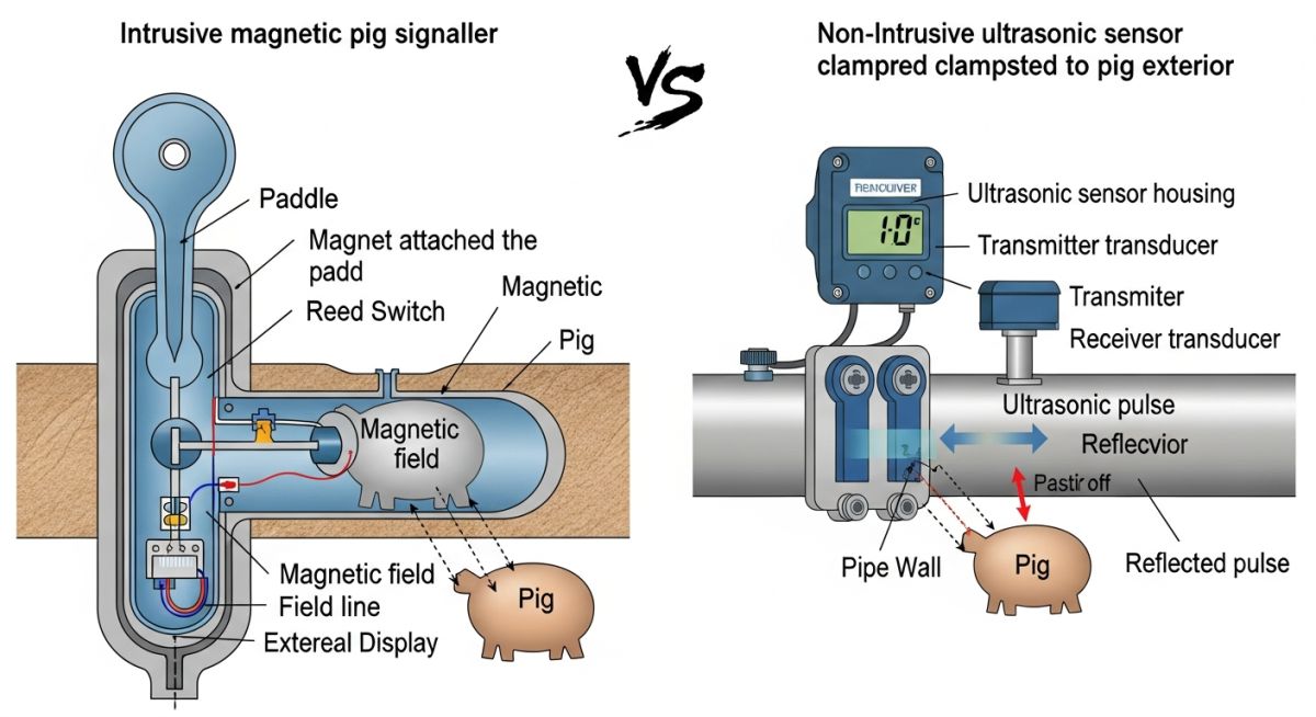
To design a reliable pigging system, we must first analyze the physical interaction between the pig and the detection device. Pig signallers are broadly categorized into two main operating designs: intrusive (mechanical trigger) and non-intrusive (magnetic, ultrasonic, or acoustic).
1. Intrusive Mechanical Signallers
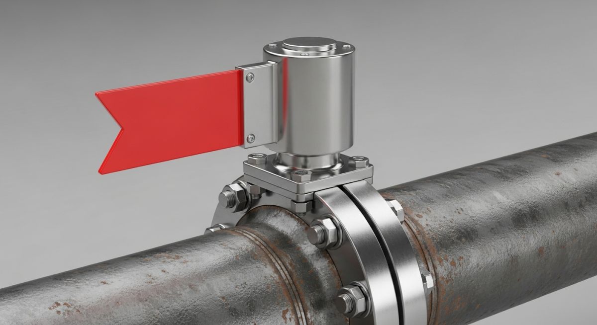
These devices feature a physical trigger or omnidirectional plunger that extends directly into the pipeline bore. When the pig passes, its body physically displaces the trigger. This displacement is transmitted through a pressure-sealed shaft to actuate a local visual flag, an electrical microswitch, or a pneumatic valve.
The mechanical force required to actuate the trigger must be carefully balanced. If the spring rate is too high, the pig may get stuck or damage its cups. If it is too low, line turbulence or high-velocity gas flow can cause false actuations. The trigger force calculation is expressed as:
Where:
• Trigger Force is the mechanical force exerted by the passing pig to actuate the signaller.
• Differential Pressure is the pressure drop across the pig body.
• Trigger Area is the projected contact area of the omnidirectional trigger.
• Spring Preload Force is the resistance force of the internal return spring.
2. Non-Intrusive Signallers
Non-intrusive signallers do not penetrate the pipeline wall, eliminating any leak paths or pressure containment risks. They are highly favored in high-pressure gas transmission lines and sour service applications.
- Magnetic Detectors: These sense the change in magnetic flux when a pig equipped with permanent magnets passes beneath the sensor. They require the pig to be fitted with a magnetic transmitter or rare-earth magnets.
- Ultrasonic Detectors: These transmit high-frequency sound waves through the pipe wall. The passage of the pig disrupts the acoustic signal, triggering an alarm. They are highly effective but require clean pipe surfaces and acoustic couplant gel.
In my experience, mechanical triggers installed in pipelines carrying abrasive slurries or high-velocity sand will experience rapid erosive wear. This wear reduces the trigger height, leading to missed pig passages. Always specify hard-faced trigger tips (such as Stellite coating) for abrasive service.
Design Standards and Code Compliance
All pressure-containing parts of an intrusive pig signaller must comply with international piping codes. The primary design codes include ASME B31.4 for liquid pipelines, ASME B31.8 for gas pipelines, and ASME B31.3 for process piping. Flanged connections must meet ASME B16.5 or ASME B16.47 standards.
Selecting Materials for Pig Signallers Safely
Selecting the correct materials for pig signallers is critical to ensuring long-term pressure containment and operational reliability. Below are the standard engineering tables I use during the front-end engineering design (FEED) phase.
Table 1: Material Selection for Intrusive Signaller Components
| Component | Standard Service | Sour Service (NACE) | Low Temp Service | Pressure Class |
|---|---|---|---|---|
| Body / Flange | ASTM A105 / A350 LF2 | ASTM A350 LF2 Class 1 | ASTM A350 LF2 CL1 | ASME 150 to 2500 |
| Trigger / Plunger | SS 316 | Inconel 625 / Duplex SS | SS 316L | N/A (Internal) |
| Internal Springs | SS 302 / 316 | Inconel X-750 | Inconel X-750 | N/A (Internal) |
| Primary Seals | Viton (FKM) | HNBR / PTFE (AED) | Low-Temp Nitrile | N/A (Internal) |
| Indicator Flag | Aluminum / SS 304 | SS 316 | SS 316 | Atmospheric |
Table 2: Technical Mapping & Specifications Matrix
| Technical Entity | Acronym | Physical Parameter | Standard Reference |
|---|---|---|---|
| Anti-Explosive Decompression | AED | Elastomer resistance to rapid gas depressurization | NORSOK M-710 |
| National Association of Corrosion Engineers | NACE | Sulfide stress cracking resistance limits | NACE MR0175 / ISO 15156 |
| Ingress Protection | IP | Enclosure sealing against dust and water ingress | IEC 60529 (IP66 / IP67 / IP68) |
| Hazardous Area Certification | ATEX / IECEx | Explosion-proof electrical enclosure design | Directive 2014/34/EU |
How to Install Pig Signallers Correctly
An improperly installed pig signaller is a major liability. If an intrusive trigger is welded out of alignment, the passing pig will either shear the trigger off or get stuck behind it. If a non-intrusive sensor is placed over a heavy internal weld seam, the signal will be completely blocked. Follow this field-tested checklist to ensure a flawless installation.
Site Verification Checklist
Ensure the intrusive signaller boss is welded perfectly perpendicular (90 degrees) to the pipeline axis. Any angular deviation will cause the trigger to bind.
Measure the internal protrusion depth of the mechanical trigger. The trigger must extend into the pipe bore by exactly 10% to 15% of the nominal pipe diameter.
Perform Dye Penetrant Testing (DP) or Magnetic Particle Testing (MPT) on the attachment weld of the mounting boss in compliance with API 1104.
Verify that the primary O-rings and backup rings are free of scratches. Apply a thin layer of system-compatible lubricant to prevent extrusion during high-pressure commissioning.
Confirm that the electrical junction box is properly grounded and that the cable glands maintain the ATEX/IECEx explosion-proof rating.
Resolving Failures in Pig Signallers Fieldwork
The Problem: False Negatives on a 24-Inch Crude Oil Pipeline
During a routine maintenance run on a 24-inch crude oil pipeline in the Middle East, the operations team reported that the mechanical pig signaller at the receiver station failed to register the arrival of a cleaning pig. This led to a false assumption that the pig was stuck in the line, prompting the team to prepare for an expensive emergency pipeline intervention.
As the lead piping engineer, I was called to the site. Upon physical inspection of the receiver, we discovered that the pig had actually arrived safely, but the signaller’s visual flag had not dropped.
The Outcome: Root Cause and Engineering Solution
We isolated the signaller using its integral ball valve mechanism and extracted the internal trigger assembly. The root cause was immediately clear: heavy paraffin wax deposition had packed tightly into the trigger cavity, completely seizing the omnidirectional plunger in the “retracted” position. The return spring did not have enough force to overcome the shear resistance of the cold wax.
To resolve this permanently, I implemented a two-step engineering solution:
- We retrofitted the mechanical signaller with an internal solvent flushing port, allowing operators to inject diesel or wax solvent directly into the trigger cavity before every pigging run.
- We installed a secondary, non-intrusive magnetic signaller as a redundant backup system, ensuring that even if the mechanical trigger seized, the magnetic flux sensor would still capture the pig’s arrival.
This dual-technology approach completely eliminated false negatives, saving the operator hundreds of thousands of dollars in unnecessary pipeline shutdowns and intervention costs.
Common Questions About Pig Signallers Answered
What is the difference between intrusive and non-intrusive pig signallers?
Can mechanical pig signallers be removed under pipeline pressure?
How do you prevent false signals caused by pipeline fluid turbulence?
What are the NACE requirements for pig signallers in sour service?
Do non-intrusive magnetic signallers work on thick-walled pipes?
What maintenance is required for mechanical pig signallers?
===FAQ_BLOCK===
Complete Course on
Piping Engineering
Check Now
Key Features
- 125+ Hours Content
- 500+ Recorded Lectures
- 20+ Years Exp.
- Lifetime Access
Coverage
- Codes & Standards
- Layouts & Design
- Material Eng.
- Stress Analysis