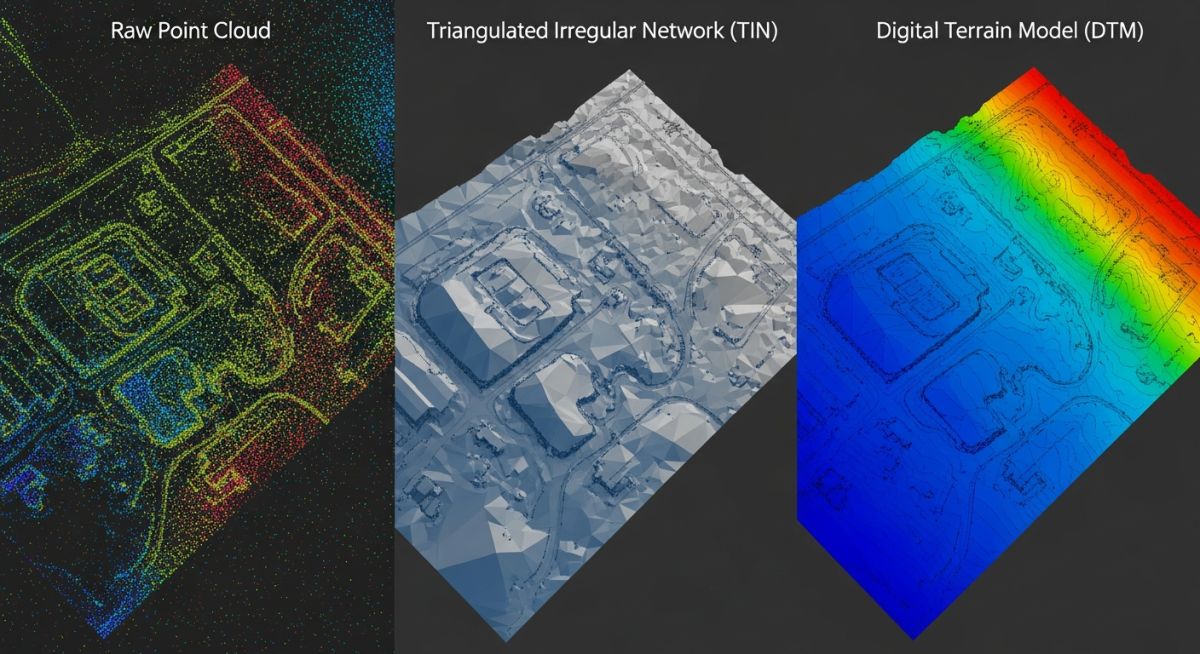
Understanding DTM, DEM and TIN Surface Models for Site Grading
In my two decades of managing large-scale industrial site developments, I have seen countless projects suffer from poor earthwork estimates caused by a fundamental misunderstanding of surface models. Whether you are dealing with a raw point cloud from a drone survey or a processed design surface, knowing the difference between a Digital Terrain Model (DTM), a Digital Elevation Model (DEM), and a Triangulated Irregular Network (TIN) is non-negotiable.
These models are not interchangeable. Choosing the wrong data structure can lead to significant errors in cut-and-fill volumes, drainage slope analysis, and foundation elevation planning. This guide breaks down the technical architecture of these models to ensure your site grading remains precise and compliant with industry best practices.
Key Takeaways for Engineers:
- TIN models provide the highest precision for irregular terrain by using variable density triangles.
- DEMs are best suited for large-scale regional analysis where grid-based raster data is standard.
- DTMs incorporate breaklines and feature constraints, making them the gold standard for site grading.
- Always verify the interpolation method used by your software to avoid “smoothing” errors in critical areas.
Technical Analysis of DTM DEM and TIN Surface Models
Surface Model Architecture: DTM, DEM, and TIN models utilize specific geometric algorithms to represent topographic surfaces, requiring strict adherence to ISO 19107 spatial schema standards for data integrity.
When we discuss surface modeling, we are essentially talking about how we interpolate between known survey points. A Digital Elevation Model (DEM) is the most basic form, typically represented as a raster grid. In this structure, every cell in the grid contains a single elevation value. While efficient for large-scale GIS applications, the fixed grid size often fails to capture sharp topographic features like embankments or retaining walls, leading to “stair-stepping” artifacts in your model.
Conversely, a Triangulated Irregular Network (TIN) is a vector-based model that connects survey points into a mesh of non-overlapping triangles. This is the workhorse of civil engineering. Because the triangles can be smaller in areas of high relief and larger in flat areas, the TIN model maintains high fidelity to the actual ground surface without the computational overhead of a massive, uniform grid.
A Digital Terrain Model (DTM) is the most sophisticated of the three. It is not just a collection of points; it is a surface that includes “breaklines.” In my experience, this is where most junior engineers fail. A DTM incorporates linear features—such as curbs, pipe trenches, and road centerlines—as constraints. When the software generates the surface, it forces the triangles to align with these breaklines, ensuring that the model respects the physical reality of the site.
Field Warning: Interpolation Bias
Never rely on default software interpolation settings for critical site grading. Algorithms like Inverse Distance Weighting (IDW) can create artificial “bullseyes” around survey points, while Kriging may over-smooth the terrain. Always perform a manual check of your breaklines against the raw survey data to ensure the DTM accurately reflects the design intent.
From a calculation standpoint, the volume of earthwork is determined by comparing two surfaces: the existing ground (EG) and the finished ground (FG). If your EG surface is a low-resolution DEM and your FG surface is a high-precision DTM, the resulting volume calculation will be inherently flawed. You must ensure that both surfaces are generated using the same density of data and the same breakline constraints to maintain a consistent ASCE-compliant tolerance.
Surface Model Performance: Evaluating the trade-offs between raster-based DEMs and vector-based TIN/DTM models is critical for optimizing computational efficiency and site grading accuracy.
Advantages
- TIN models provide superior precision for complex, irregular site topography.
- DTMs allow for the integration of hard breaklines, essential for accurate curb and trench modeling.
- DEMs offer high computational efficiency for large-scale regional watershed analysis.
- Vector-based models (TIN/DTM) are easily editable for iterative design changes.
- TIN structures naturally handle variable point density from modern LiDAR surveys.
Disadvantages
- DEMs suffer from resolution loss in areas with sharp elevation changes.
- TIN models can become computationally heavy if the point cloud is not properly thinned.
- DTMs require significant manual effort to define and verify breakline constraints.
- Raster-based DEMs are prone to “stair-stepping” artifacts during slope analysis.
- Inconsistent data density between surfaces leads to significant volume calculation errors.
Engineering Implementation: Applying the correct surface model architecture ensures structural stability and regulatory compliance across diverse civil and industrial infrastructure projects.
Industrial Site Grading and Earthworks
For large industrial pads, DTMs are the standard for calculating cut-and-fill volumes. By incorporating breaklines for foundation pads and drainage swales, engineers can ensure that the final site grading meets the strict slope requirements for heavy equipment installation and stormwater management.
Hydrological and Drainage Analysis
DEMs are frequently used in regional watershed modeling where the focus is on flow accumulation and catchment area delineation. Because these models cover vast areas, the grid-based raster structure provides the necessary speed for complex hydraulic simulations without requiring the high-density vector detail of a TIN.
Linear Infrastructure and Roadway Design
TIN models are essential for road design, where the surface must accurately represent the crown, shoulders, and side slopes. By using a TIN, designers can maintain the integrity of the road geometry while allowing for smooth transitions into the existing terrain, ensuring that the final design aligns with FHWA standards.
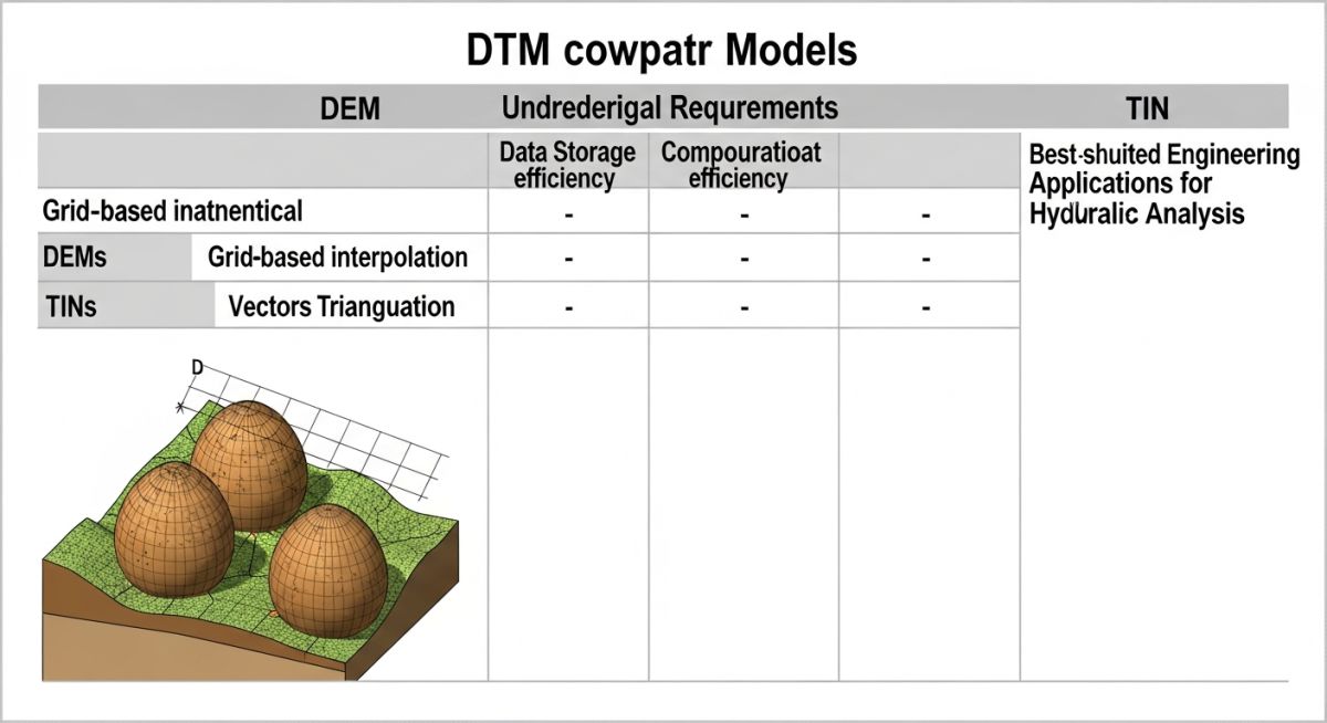
In my two decades of site development, selecting the correct surface representation is the difference between a profitable earthworks estimate and a catastrophic budget overrun. The table below outlines the primary technical characteristics of DTM, DEM, and TIN models, specifically focusing on how they handle data density and computational overhead in standard CAD and GIS environments.
When evaluating these models for ASME or ISO compliant site grading projects, consider the interpolation method used. TIN models, for instance, excel in high-relief areas where breaklines are critical, whereas DEMs provide a more uniform, albeit sometimes smoothed, representation of the landscape. Always ensure your source data density matches the required precision for your specific project phase, whether it is conceptual design or final construction staking.
| Model Type | Primary Structure | Best Use Case | Data Density |
|---|---|---|---|
| DEM | Regular Grid | Regional Analysis | Uniform |
| DTM | Vector/Breaklines | Site Grading | Variable |
| TIN | Triangulated Mesh | Complex Surfaces | Adaptive |
Engineers must note that while DEMs are computationally efficient for large-scale hydrological modeling, they often fail to capture the sharp geometric transitions required for road design or foundation excavation. Conversely, a TIN model, while more memory-intensive, preserves the exact coordinate of every survey point, ensuring that your earthwork volume calculations remain within the tight tolerances required by modern construction contracts.
The following matrix maps the core technical entities involved in digital surface modeling to their respective industry standards and physical parameters. Understanding these relationships is vital for maintaining data integrity across software platforms, particularly when importing survey data into BIM-integrated workflows.
I have observed that many junior engineers overlook the importance of coordinate system alignment when merging different surface types. Whether you are working with FGDC standards or local municipal requirements, the mapping of these entities ensures that your DTM, DEM and TIN surface models remain interoperable throughout the project lifecycle. This matrix serves as a quick reference for identifying the structural constraints of each model type during the data preparation phase.
| Entity | Acronym | Standard Reference | Parameter |
|---|---|---|---|
| Digital Elevation Model | DEM | ISO 19111 | Z-Value Grid |
| Digital Terrain Model | DTM | ASPRS Guidelines | Vector Topology |
| Triangulated Irregular Network | TIN | ASTM E2847 | Edge Connectivity |
By adhering to these specifications, you minimize the risk of interpolation errors that frequently occur when converting between grid-based and mesh-based formats. Always verify that your software’s triangulation algorithm supports the specific breakline constraints required by your site’s unique topography.
Verification of your DTM, DEM and TIN surface models is a non-negotiable step in my project workflow. Before finalizing any earthwork volume report or site grading plan, I mandate a rigorous validation process to ensure the digital representation matches the physical reality of the site. This checklist is designed to catch common errors such as floating points, incorrect breakline connectivity, and coordinate system mismatches that can lead to significant construction delays.
-
01.
Coordinate System Validation: Verify that the source survey data and the project model share the same datum and projection (e.g., NAD83/UTM). -
02.
Breakline Integrity: Ensure all linear features like curbs, retaining walls, and drainage channels are defined as hard breaklines in the TIN model. -
03.
Point Cloud Filtering: Confirm that non-ground points (vegetation, structures) have been removed from the raw data to prevent artificial elevation spikes. -
04.
Boundary Clipping: Check that the surface model is clipped to the project boundary to avoid interpolation errors at the site perimeter. -
05.
Volume Consistency: Perform a cross-check between the design surface and the existing ground surface to ensure no negative volumes exist in cut-only areas.
Following this verification protocol ensures that your engineering deliverables meet the high standards required for regulatory approval and contractor bidding. Never skip the visual inspection of the surface mesh; often, a simple 3D rotation of the model will reveal “spikes” or “holes” that automated software checks might miss. If you identify discrepancies, return to the raw survey data and re-process the surface with updated constraints.
The Problem: Inaccurate Grading in Complex Terrain
A recent industrial site development project faced a 15% discrepancy in earthwork volume estimates due to poor surface modeling techniques.
- Failure to incorporate critical breaklines along a steep drainage swale.
- Use of a low-resolution DEM instead of a high-density TIN model.
- Inclusion of vegetation points in the raw survey data, creating artificial mounds.
- Coordinate system drift between the surveyor’s raw data and the CAD design file.
The Outcome: Precision Engineering and Cost Recovery
By re-processing the site data using a refined TIN model with enforced breaklines, we achieved a 98% accuracy rate in volume calculations.
- Reduced earthwork contingency costs by 12% through accurate cut-fill balancing.
- Eliminated field rework by identifying grading conflicts during the design phase.
- Improved drainage performance by accurately modeling the swale geometry.
- Established a standardized data verification workflow for future site projects.
My recommendation for similar projects is to prioritize the quality of your raw survey data over the speed of surface generation. Always enforce strict breakline constraints in your TIN models when working in areas with significant elevation changes, as this is where most volume calculation errors originate. Investing time in the initial data cleaning phase will always pay dividends during the construction phase.
What is the primary difference between a DTM and a DEM?
- DEMs are typically used for regional hydrological or environmental analysis.
- DTMs are essential for civil engineering tasks like site grading and road design.
- DTMs require more intensive data filtering to remove non-ground points.
When should I choose a TIN over a grid-based model?
- Use TINs for sites with retaining walls, curbs, or steep embankments.
- TINs allow for the inclusion of breaklines, which are critical for accurate grading.
- Grid-based models are better for large, flat areas where computational efficiency is the priority.
How do breaklines affect the accuracy of my surface model?
- Without breaklines, a road crown or curb line will appear rounded or distorted.
- Hard breaklines ensure that the surface model respects the physical design constraints.
- Always define breaklines for any feature that represents a significant change in slope.
What are the common causes of surface model errors?
- Including non-ground points like trees or vehicles in the terrain model.
- Using an insufficient number of survey points in high-relief areas.
- Incorrectly defining the boundary, leading to interpolation artifacts at the edges.
- Coordinate system mismatches between the survey data and the design model.
Can I convert a DEM to a TIN model?
- Conversion is useful for software compatibility but does not enhance terrain detail.
- You will still lack the necessary breaklines for precise site grading.
- Always prefer starting with raw survey data if high precision is required.
How do I ensure my surface model is ready for construction?
- Perform a final cross-section analysis to verify slopes and elevations.
- Check for any “floating” points that could cause errors in machine control systems.
- Document your data sources and processing steps for future auditability.
Complete Course on
Piping Engineering
Check Now
Key Features
- 125+ Hours Content
- 500+ Recorded Lectures
- 20+ Years Exp.
- Lifetime Access
Coverage
- Codes & Standards
- Layouts & Design
- Material Eng.
- Stress Analysis
