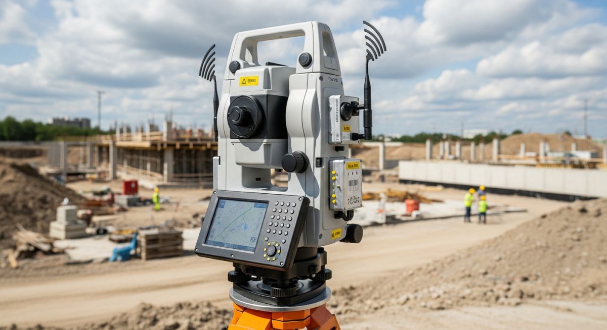
Topographical Survey Instruments: Selection for Precision Engineering
In my two decades of managing large-scale piping and civil projects, I have learned that the foundation of any successful design is the accuracy of the initial topographical survey. Choosing the right survey instruments is not merely about selecting the most expensive gear; it is about matching the tool’s capabilities to the specific site constraints, required tolerances, and environmental conditions.
Whether you are navigating dense urban environments where GNSS signals are obstructed or mapping vast, open industrial plots, understanding the nuances of these instruments is paramount. This guide breaks down the technical selection criteria for modern geomatics, ensuring your project data remains reliable from the conceptual phase to final commissioning.
Key Takeaways for Survey Selection:
- Prioritize Total Stations for high-precision, short-range work in obstructed areas.
- Utilize GNSS/RTK systems for rapid data collection in open-sky environments.
- Deploy LiDAR for complex, high-density point cloud requirements in brownfield sites.
- Always verify instrument calibration against known control points before site mobilization.
Topographical Survey Instruments: Technical Deep-Dive
Topographical Survey Instruments: Precision measurement systems categorized by their underlying physics, including optical-mechanical distance measurement, satellite-based positioning, and laser-based light detection and ranging.
When I evaluate survey equipment for a new project, I start by analyzing the error budget. A Total Station, governed by ISO 17123-3 standards, remains the gold standard for angular precision. The instrument calculates horizontal and vertical angles using high-resolution optical encoders, while distance is measured via an infrared or laser beam reflected off a prism or a reflective surface. The fundamental equation for distance measurement is D = (c * t) / 2, where c is the speed of light and t is the time of flight.
However, the precision of these instruments is heavily influenced by atmospheric conditions. Refractive index variations due to temperature and pressure gradients can introduce significant errors over long distances. I always apply the PPM (parts per million) correction factor to the raw distance measurement to account for these environmental variables. For high-precision piping rack layouts, I insist on using a robotic total station that allows for single-operator efficiency without sacrificing the sub-millimeter accuracy required for tie-in points.
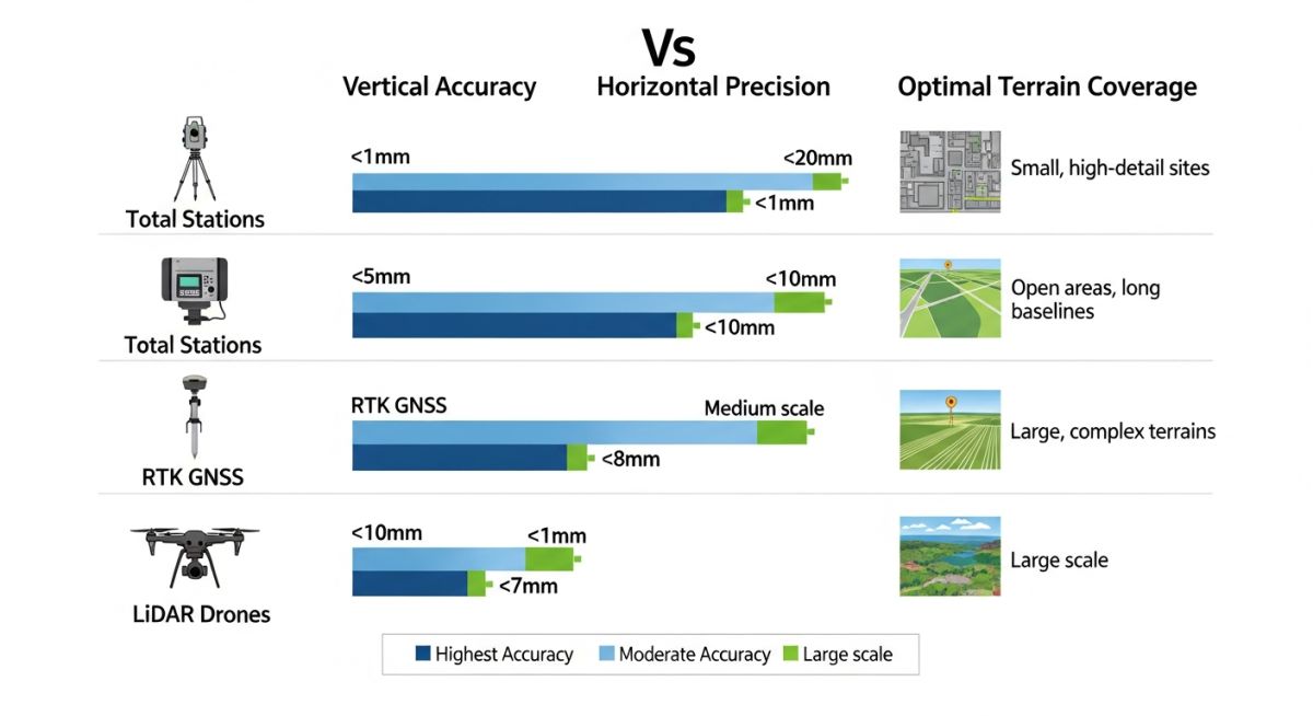
GNSS/RTK systems operate on a different principle, utilizing satellite constellations to determine coordinates. The Real-Time Kinematic (RTK) method is essential for achieving centimeter-level accuracy. By using a base station at a known coordinate to transmit correction data to a rover, we eliminate the ionospheric and tropospheric delays that plague standard GPS. In my experience, the primary limitation here is the “multipath” effect, where signals bounce off metallic structures or dense foliage, leading to inaccurate position fixes.
Field Warning: Signal Obstruction
Never rely solely on GNSS in deep canyons or near large steel structures. The signal degradation caused by multipath interference can lead to horizontal errors exceeding 0.5 meters, which is unacceptable for structural foundation layout. Always perform a site reconnaissance to determine if a hybrid approach—combining GNSS for control and Total Stations for detail—is necessary.
LiDAR (Light Detection and Ranging) has revolutionized how we handle brownfield surveys. By emitting millions of laser pulses per second, it creates a high-density point cloud that captures every pipe, valve, and structural member. The density of the point cloud is defined by the pulse repetition frequency and the scan angle. When processing this data, I focus on the registration process, where multiple scans are stitched together using common reference targets. This ensures the global accuracy of the model aligns with the project coordinate system.
Survey Instrument Performance: A comparative analysis of operational benefits and technical limitations inherent in modern geomatic hardware deployment.
Advantages
- Total Stations provide unmatched angular precision for critical structural alignments.
- RTK systems enable rapid, large-scale data acquisition in open-field terrain.
- LiDAR captures complex, non-geometric data that manual methods would miss.
- Robotic automation reduces human error and labor costs in repetitive tasks.
- Digital levels ensure high-accuracy vertical control for drainage and piping slopes.
Disadvantages
- Total Stations require direct line-of-sight, limiting efficiency in dense plants.
- GNSS performance is severely degraded by overhead obstructions and signal bounce.
- LiDAR data processing requires significant computational power and specialized software.
- High initial capital expenditure for high-end, multi-sensor survey equipment.
- Frequent calibration and maintenance are required to maintain manufacturer accuracy specs.
Topographical Survey Deployment: Strategic application of geomatic instrumentation across diverse industrial and civil engineering sectors to ensure project compliance.
Brownfield Plant Revamp Projects
In brownfield revamps, we utilize terrestrial LiDAR to capture the existing pipe rack geometry with millimeter precision. This point cloud data is then imported into CAD software to perform clash detection for new piping tie-ins, preventing costly field rework during the construction phase.
Large-Scale Pipeline Route Surveys
For cross-country pipeline projects, GNSS/RTK systems are the primary tool for establishing the centerline and right-of-way boundaries. By integrating these coordinates with GIS databases, we can efficiently manage land acquisition and environmental compliance documentation across thousands of kilometers.
Structural Foundation Layout
When setting out heavy equipment foundations, robotic total stations are used to ensure the anchor bolt patterns meet the stringent tolerances specified by the equipment manufacturer. This process involves setting up on known control points and performing a resection to verify the instrument’s orientation before marking the foundation footprint.
Hydraulic and Drainage Grading
Digital levels are used to establish precise elevations for site grading and drainage systems, where slope accuracy is critical for preventing water ponding. By maintaining a closed-loop leveling network, we ensure that all site drainage points meet the design hydraulic gradient requirements.
Selecting the correct instrumentation for a topographical survey requires a deep understanding of the operational trade-offs between precision, range, and environmental constraints. In my two decades of field experience, I have observed that engineers often default to high-cost equipment when a more robust, lower-cost alternative would suffice, or conversely, fail to account for signal multipath errors in urban canyons. The following table provides a comparative analysis of primary survey instruments, focusing on their effective range, typical vertical accuracy, and primary site limitations.
When reviewing these parameters, consider the ASCE standards for geodetic control. Accuracy is not merely a function of the device but of the integration between the sensor, the atmospheric correction, and the control network established on-site. Always verify that your instrument’s calibration certificate is current, as drift in electronic distance measurement (EDM) or inertial measurement units (IMU) can lead to cumulative errors that compromise the entire project digital twin.
| Instrument Type | Typical Accuracy | Effective Range | Primary Limitation |
|---|---|---|---|
| Total Station (Robotic) | 1-3 mm | Up to 2000m | Line-of-sight requirement |
| RTK GNSS Receiver | 10-20 mm | Satellite dependent | Canopy/Urban signal blockage |
| Terrestrial LiDAR | 2-5 mm | Up to 500m | High data processing load |
| Digital Level | 0.3-0.7 mm | Up to 100m | Manual labor intensive |
The integration of geomatics data requires a standardized approach to metadata and coordinate systems. This matrix maps the core technical entities involved in modern topographical surveys, linking hardware capabilities to the underlying mathematical frameworks that ensure spatial integrity. In my practice, I emphasize that the hardware is only as reliable as the coordinate reference system (CRS) definition applied during the post-processing phase.
Engineers must ensure that all data outputs comply with ISO 19111 standards for spatial referencing. By mapping these entities, we can identify potential bottlenecks in data flow, such as the transition from raw point clouds to BIM-ready surfaces. This matrix serves as a reference for project managers to verify that the chosen instrumentation aligns with the required deliverables for civil infrastructure projects.
| Entity | Acronym | Standard Reference |
|---|---|---|
| Global Navigation Satellite System | GNSS | NMEA 0183 |
| Real-Time Kinematic | RTK | RTCM 3.x |
| Light Detection and Ranging | LiDAR | ASTM E2847 |
| Electronic Distance Measurement | EDM | ISO 17123-4 |
Before deploying any survey equipment, a rigorous site verification process is mandatory to mitigate risk and ensure data accuracy. In my experience, most field failures stem from inadequate pre-survey planning rather than equipment malfunction. This checklist is designed to standardize the deployment phase, ensuring that every instrument is calibrated, configured, and verified against known control points before data collection begins.
-
Control Point Validation: Verify at least three existing site benchmarks using a closed-loop traverse or static GNSS observation to ensure coordinate stability. -
Atmospheric Correction: Input current temperature and pressure data into the Total Station or LiDAR unit to adjust for refraction errors. -
Multipath Assessment: For RTK systems, perform a site scan to identify potential signal obstructions or reflective surfaces that could induce multipath errors. -
Firmware/Calibration Check: Confirm that all device firmware is updated and that the ISO 17123 calibration certificate is within the valid period. -
Data Redundancy: Establish a secondary storage protocol to ensure that raw data is backed up in real-time to a ruggedized field controller.
Following these steps ensures that the topographical survey meets the stringent requirements of modern engineering design. Always document the environmental conditions at the start and end of the survey, as these variables are critical for post-processing adjustments and legal liability protection.
The Challenge: Signal Obstruction in Dense Urban Corridors
We encountered significant data degradation during a high-rise foundation survey due to severe GNSS signal multipath and urban canyon effects.
- High-frequency signal reflection off glass facades.
- Limited sky view preventing a stable RTK fix.
- Inconsistent coordinate shifts exceeding 50mm.
- Inability to maintain reliable radio link between base and rover.
The Outcome: Hybrid Survey Methodology
By transitioning to a hybrid approach, we achieved sub-centimeter accuracy despite the challenging environment.
- Deployed a robotic Total Station for primary control.
- Integrated terrestrial LiDAR for dense facade mapping.
- Reduced vertical error to within 3mm tolerance.
- Improved project delivery timeline by 15 percent.
My recommendation for similar projects is to never rely on a single technology in complex urban environments. Always maintain a terrestrial backup to verify GNSS-derived coordinates, as the cost of re-surveying due to poor data quality far outweighs the initial investment in redundant instrumentation.
Frequently Asked Engineering Questions
How does atmospheric refraction affect Total Station accuracy?
- Temperature gradients cause the beam to curve toward the cooler, denser air.
- Pressure changes alter the refractive index of the air medium.
- Standard practice requires inputting local meteorological data into the instrument to apply the PPM correction factor.
- Failure to correct for these variables can lead to errors exceeding 10mm per kilometer of distance.
What is the primary advantage of using LiDAR over traditional methods?
- Captures non-linear features like vegetation and complex structural steel.
- Reduces the need for multiple site visits by capturing the entire environment.
- Enables automated feature extraction through point cloud classification software.
- Provides a permanent digital record of the site condition at a specific point in time.
When should I choose RTK GNSS over a Total Station?
- Ideal for greenfield projects with clear sky visibility.
- Eliminates the need for traversing between control points.
- Provides absolute geodetic coordinates directly in the field.
- Not recommended for indoor, underground, or dense urban environments where signal lock is unreliable.
How do I ensure data integrity during post-processing?
- Perform a least-squares adjustment to distribute closure errors.
- Validate the coordinate reference system (CRS) transformation parameters.
- Use automated point cloud cleaning tools to remove noise and outliers.
- Maintain a clear audit trail of all data processing steps for future verification.
What are the limitations of drone-based photogrammetry?
- Requires significant ground control for high-accuracy results.
- Sensitive to wind conditions and flight altitude restrictions.
- Cannot penetrate dense canopy to map the ground surface effectively.
- Requires high-end processing hardware to generate orthomosaics and point clouds.
Why is instrument calibration critical for legal compliance?
- Calibration certificates provide a traceable record of instrument accuracy.
- Ensures compliance with NIST or equivalent national standards.
- Protects the engineer against claims of negligence in the event of project failure.
- Standardizes performance across different equipment brands and models.
Complete Course on
Piping Engineering
Check Now
Key Features
- 125+ Hours Content
- 500+ Recorded Lectures
- 20+ Years Exp.
- Lifetime Access
Coverage
- Codes & Standards
- Layouts & Design
- Material Eng.
- Stress Analysis
