Table of Contents
Mastering Piping Stress Interview Questions: The Ultimate Engineering Guide
Over my 20 years in the piping design industry, I have sat on both sides of the interview table. I have designed piping systems for massive petrochemical complexes, offshore platforms, and high-pressure steam plants. I know exactly what hiring managers look for when they grill candidates on piping stress analysis. They do not just want textbook definitions; they want to see if you have faced the gritty realities of field failures, nozzle overloads, and complex thermal expansion problems.
This guide is designed to prepare you for the toughest technical interviews. We will dive deep into code requirements, stress calculations, and practical support selection. Whether you are preparing for a senior stress engineer role or looking to solidify your design fundamentals, this comprehensive breakdown will give you the technical edge you need.
What You Will Master in This Guide:
- The exact mathematical formulations for sustained, occasional, and expansion load cases.
- How to apply ASME B31.3 code compliance rules to real-world piping layouts.
- Practical strategies for mitigating high nozzle loads on sensitive rotating equipment.
- A complete site verification checklist to ensure your stress models match field conditions.
How to Ace Piping Stress Interview Questions
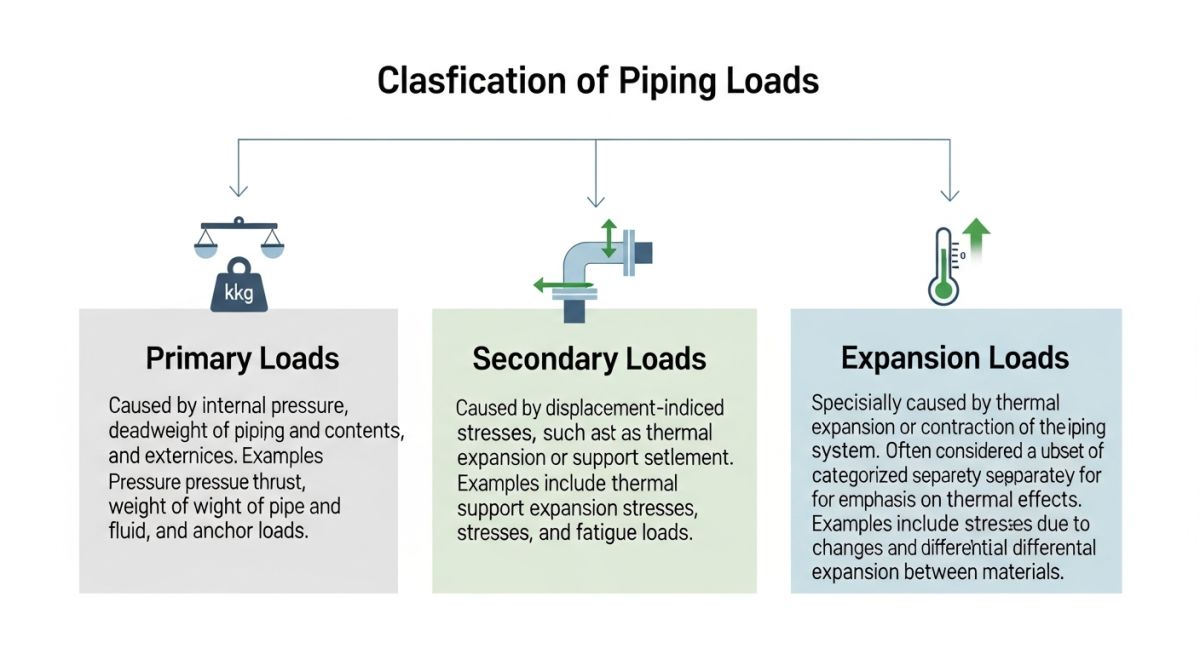
In my experience, the core of any piping stress interview revolves around how you classify and calculate loads. Piping systems experience three primary types of loads: sustained, occasional, and expansion. Understanding the physical behavior of the piping under these loads is what separates a junior modeler from a senior stress specialist.
1. Sustained Loads (Weight and Pressure)
Sustained loads are constant forces that act on the piping system throughout its operational life. These are primarily caused by internal design pressure and the weight of the pipe, insulation, fluid, and inline components like valves and flanges. The longitudinal stress caused by sustained loads must not exceed the hot allowable stress of the material.
S_L = (P * D_o) / (4 * t) + (0.75 * i * M_A) / Z <= S_h
Where:
• P = Internal design pressure
• D_o = Outside diameter of the pipe
• t = Nominal wall thickness minus corrosion allowance
• i = Stress intensification factor (SIF)
• M_A = Resultant bending moment due to sustained weight loads
• Z = Section modulus of the pipe
• S_h = Basic allowable stress at the maximum metal temperature
2. Occasional Loads (Wind and Seismic)
Occasional loads are temporary, short-duration forces acting on the piping. These include wind loads, seismic accelerations, water hammer, and relief valve discharge thrust. ASME B31.3 allows a temporary increase in the allowable stress limit (typically 33% higher than sustained limits) for these short-duration events.
3. Expansion Loads (Thermal Displacement)
Unlike sustained loads, thermal expansion loads are self-limiting. When a pipe heats up, it expands. If this expansion is restricted by anchors or guides, thermal stresses develop. The system relieves these stresses through local yielding or displacement. The displacement stress range is calculated using the following formula:
S_E = sqrt(S_b^2 + 4 * S_t^2) <= S_A
Where S_b is the resultant bending stress, S_t is the torsional stress, and S_A is the allowable displacement stress range, defined as:
S_A = f * (1.25 * S_c + 0.25 * S_h)
Where S_c is the basic allowable stress at the minimum metal temperature, and f is the stress range reduction factor based on the total number of thermal cycles over the design life.
Never ignore the impact of friction on piping supports. High friction coefficients can transfer massive, unexpected thrust loads to sensitive equipment nozzles, leading to casing distortion, shaft misalignment, or catastrophic seal failures. Always evaluate the use of PTFE or graphite slide plates for heavy, high-temperature lines.
Standard Allowable Stress Limits for Piping
During technical interviews, you may be asked to compare how different load cases are evaluated. The table below outlines the standard stress limits and code references that every piping stress engineer must know by heart.
| Load Case Type | Primary Cause | ASME B31.3 Code Limit | Failure Mode Prevented |
|---|---|---|---|
| Sustained | Weight, Internal Pressure | S_h (Hot Allowable Stress) | Gross plastic deformation, rupture |
| Occasional | Wind, Earthquake, Relief Valve | 1.33 * S_h | Structural collapse, buckling |
| Expansion | Thermal Growth, Displacement | S_A (Allowable Stress Range) | Fatigue failure, local yielding |
To help you navigate complex design parameters, I have compiled this technical mapping matrix. It links key physical parameters to their corresponding industry standards and analytical software inputs.
| Physical Parameter | Engineering Acronym | Governing Standard | Analytical Software Input |
|---|---|---|---|
| Stress Intensification Factor | SIF | ASME B31.3 Appendix D / B31J | Fitting Type, Intersection Geometry |
| Centrifugal Pump Nozzle Loads | NPSL | API 610 Table 5 | Nozzle Coordinates, Allowable Forces |
| Reciprocating Compressor Vibration | RCV | API 618 | Pulsation Study, Dynamic Stiffness |
| Spring Hanger Selection | SHS | MSS SP-58 | Operating Load, Thermal Travel |
Critical Steps for Piping Stress Verification
Before any piping stress analysis model is finalized and signed off for construction, a rigorous verification process must be completed. In my practice, I have seen minor modeling discrepancies lead to major field modifications. Use this checklist to ensure your designs are robust and field-ready.
Piping Stress Analysis Quality Checklist
-
Verify Design Parameters: Cross-check design pressure, operating temperature, and corrosion allowance with the latest Process Flow Diagrams (PFDs) and Piping & Instrumentation Diagrams (P&IDs).
-
Confirm Support Types and Locations: Ensure that the physical supports installed in the field match the boundary conditions (rigid, guide, spring, anchor) used in the Caesar II or AutoPIPE model.
-
Validate Nozzle Load Compliance: Confirm that all equipment nozzle loads (pumps, turbines, vessels) are within the allowable limits specified by API 610, API 617, or ASME Section VIII.
-
Check Expansion Joint Settings: If bellows or expansion joints are used, verify that their spring rates, pressure thrust areas, and tie-rod configurations are correctly modeled.
-
Review SIF and Branch Connections: Ensure that the correct Stress Intensification Factors (SIFs) are applied to all tees, reducers, and branch connections per ASME B31J.
Advanced Piping Stress Interview Questions and Answers
When interviewing for senior roles, you will inevitably face scenario-based questions. Interviewers want to know how you handle high-pressure situations where standard design rules fail. Let me share a real-world case study from a refinery expansion project I managed, which perfectly illustrates the practical application of stress analysis.
Field Case Study: Real-World Application
During the commissioning of a high-temperature steam line (450°C, 42 bar) connected to a steam turbine nozzle, the field team reported that the turbine casing was experiencing severe vibration and shaft misalignment. The initial stress model showed that the nozzle loads were within “allowable” limits, but the model had assumed a perfectly rigid foundation and ignored the thermal growth of the turbine casing itself.
I stepped in and remodeled the system by incorporating the precise thermal growth of the turbine nozzle (obtained from the OEM data sheet) and modeling the actual stiffness of the turbine support structure. The updated analysis revealed that the nozzle was experiencing a bending moment 300% higher than the API 611 allowable limit.
To resolve this, we redesigned the piping layout by adding a 3D expansion loop near the turbine and replacing two rigid guides with variable spring hangers. This modification reduced the nozzle loads to 75% of the allowable limit, completely eliminating the vibration and misalignment issues.
This case study highlights why you must never treat equipment nozzles as simple rigid anchors in your software. Always request the equipment thermal growth data and allowable nozzle loads directly from the manufacturer.
Frequently Asked Engineering Questions
What is the difference between ASME B31.1 and ASME B31.3?
How do you calculate the piping guide spacing?
What is the significance of cold spring in piping stress analysis?
How do you handle piping stress on reciprocating compressor nozzles?
What are the primary differences between active and passive piping supports?
When is a dynamic stress analysis required instead of a static analysis?
Complete Course on
Piping Engineering
Check Now
Key Features
- 125+ Hours Content
- 500+ Recorded Lectures
- 20+ Years Exp.
- Lifetime Access
Coverage
- Codes & Standards
- Layouts & Design
- Material Eng.
- Stress Analysis

📚 Recommended Resources: piping stress interview questions
Read these Guides
🎓 Advanced Training


Related posts:
![Industrial steam jet ejector 3D CAD model showing inlet and discharge ports]()
What is an Ejector? Types, Parts, Datasheet, and Working Principles
![3D CAD model of industrial piping system showing color-coded piping classes and specifications.]()
Mastering the Piping Material Specification for Industrial Plant Design
![Industrial pig launcher and receiver station with quick-opening closure and bypass piping.]()
Design and Engineering of Pig Launchers and Receivers
![Close-up of an industrial dial pressure gauge mounted on a stainless steel pipe.]()
What is a Pressure Gauge and How Does It Work?
![3D cutaway diagram of an industrial ball valve showing internal components like the ball, stem, and seats.]()
What is a Ball Valve? Design, Types, and Engineering Standards
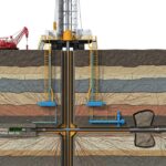
![3D cross-section diagram of a hydraulic fracturing rig drilling into underground shale rock formations.]()
What is Fracking and How Does Hydraulic Fracturing Work?