What is an Ejector? Types, Parts, Datasheet, and Working Principles
In my 20-plus years of commissioning vacuum systems in petrochemical plants, I have seen many engineers struggle with the simplicity of the ejector. They look for moving parts, shafts, or impellers, only to find a static piece of pipe. But do not let that simplicity fool you. Designing and operating a steam jet ejector system requires a deep understanding of fluid dynamics, thermodynamics, and phase changes. I remember a project in a refinery where a minor deviation in steam quality completely crippled our vacuum distillation column. That is when you realize that the humble ejector is actually a highly engineered precision instrument.
- No moving parts means exceptionally low maintenance and high reliability in harsh environments.
- Motive steam quality must be kept at 100% dry saturated or slightly superheated to prevent nozzle erosion.
- Ejectors can handle corrosive, explosive, or solid-laden streams that would destroy mechanical vacuum pumps.
- Proper alignment of the motive nozzle and diffuser is critical to maintaining the Venturi effect.
What is an Ejector Working Principle Explained
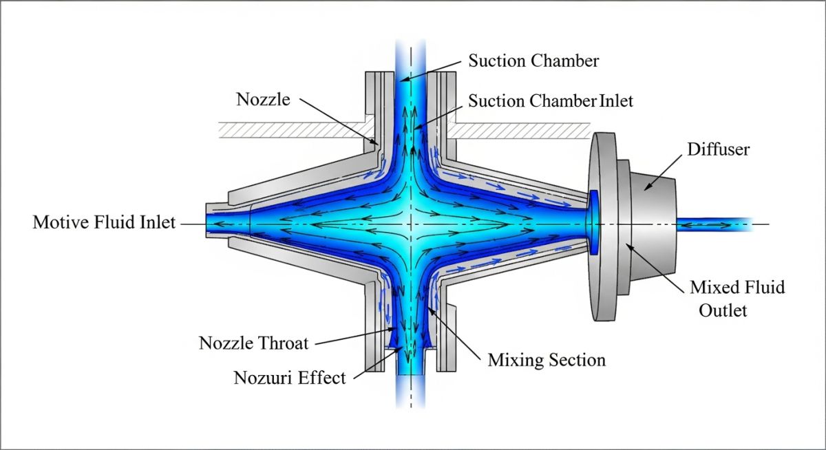
To understand how an ejector works, we must look at the conservation of energy. When a high-pressure motive fluid (typically steam, gas, or liquid) enters the converging-diverging motive nozzle, its static pressure energy is converted into kinetic energy. As the fluid passes through the nozzle throat, it reaches sonic velocity (Mach 1), and as it expands in the diverging section, it accelerates to supersonic velocities, often between Mach 1.5 and Mach 3.
This high-velocity jet exits the nozzle and enters the suction chamber, creating an extremely low-pressure zone. The process fluid from the suction inlet is drawn into this low-pressure zone and entrained by the motive fluid. The two streams mix in the mixing section, where momentum is transferred from the high-velocity motive fluid to the low-velocity suction fluid.
The mixture then enters the diffuser. In the converging section of the diffuser, the velocity is slightly reduced. In the throat and diverging section of the diffuser, the kinetic energy of the mixture is converted back into static pressure energy. This process, known as recompression, allows the mixture to discharge at a pressure higher than the suction pressure, overcoming the system backpressure.
In my experience, wet steam is the number one killer of ejector performance. Water droplets traveling at supersonic speeds act like tiny bullets, rapidly eroding the motive nozzle throat. A mere 1% increase in the nozzle throat area can lead to a catastrophic loss of vacuum. Always ensure a high-efficiency steam separator is installed upstream.
Key Design Calculations and Formulas
The design of an ejector is governed by thermodynamic and fluid dynamic equations. The velocity of the motive fluid exiting the nozzle can be calculated using the enthalpy drop:
V_1 = √(2000 × η × (h_1 – h_2))
Where:
• V_1 = Nozzle exit velocity (m/s)
• η = Nozzle efficiency (typically 0.85 to 0.95)
• h_1 = Enthalpy of motive fluid at inlet (kJ/kg)
• h_2 = Enthalpy of motive fluid at nozzle exit pressure under isentropic expansion (kJ/kg)
The Entrainment Ratio (Rm), which defines the mass of suction fluid entrained per unit mass of motive fluid, is a critical performance metric:
Rm = W_s / W_m
Where W_s is the mass flow rate of the suction fluid (kg/h) and W_m is the mass flow rate of the motive fluid (kg/h). This ratio is highly dependent on the compression ratio (Rc), defined as the discharge pressure divided by the suction pressure.
For detailed design guidelines, engineers must refer to the ASME PTC 24 standard for atmospheric ejectors and the Heat Exchange Institute (HEI) standards for steam jet vacuum systems.
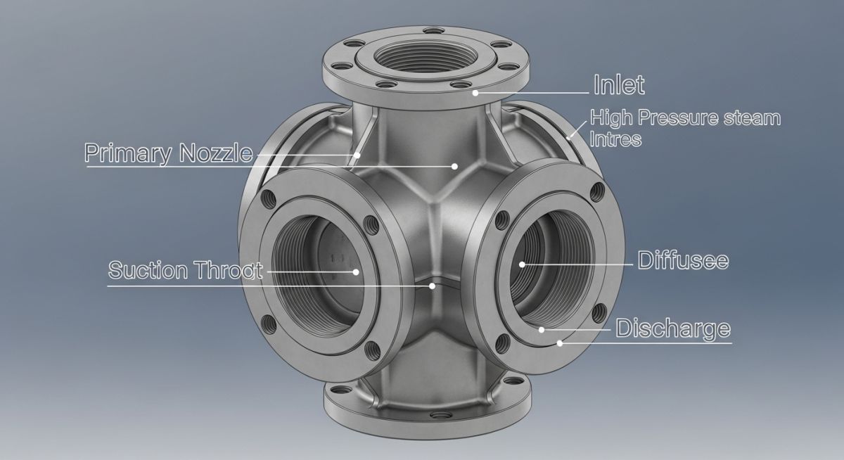
| Component Name | Primary Function | Common Materials | Design Standards |
|---|---|---|---|
| Motive Nozzle | Converts pressure energy into kinetic energy; accelerates motive fluid to supersonic speeds. | 316L SS, Monel, Hastelloy C276, Titanium | ASME B16.5, HEI Standards |
| Suction Chamber | Houses the nozzle and provides the inlet path for the process fluid to enter the low-pressure zone. | Carbon Steel (A105/A106), 304 SS, PTFE Lined | ASME Section VIII Div 1 |
| Diffuser (Inlet & Throat) | Mixes the fluids and begins the conversion of kinetic energy back into pressure energy. | Carbon Steel, 316 SS, Chrome-Moly | ASME Section VIII Div 1 |
| Diffuser (Outlet) | Diverging section that completes recompression to discharge pressure. | Carbon Steel, 316 SS | ASME B16.5 |
| Parameter | Acronym | Physical Unit | Standard Reference | Operational Impact |
|---|---|---|---|---|
| Motive Pressure | Pm | barg / psig | HEI Vacuum Standards | Must be maintained above critical pressure to prevent flow instability. |
| Suction Pressure | Ps | mbarA / mmHgA | ASME PTC 24 | Determines the vacuum level achieved in the process vessel. |
| Discharge Pressure | Pd | barg / mbarA | HEI Vacuum Standards | Maximum backpressure the ejector can operate against before breaking. |
| Entrainment Ratio | Rm | Dimensionless | Process Datasheet | Directly measures the efficiency and steam consumption of the system. |
How to Inspect and Verify Ejector Installations
Before starting up any vacuum system, a rigorous physical inspection is required. In my years on site, I have seen simple installation errors—like installing an ejector backward or omitting a steam strainer—delay plant startups by weeks. Use this checklist to verify your installation.
-
Motive Steam Quality: Verify that a steam separator and a working thermodynamic steam trap are installed within 3 meters of the ejector inlet.
-
Piping Alignment & Stress: Ensure that the suction and discharge piping are fully supported. The ejector body must not act as a pipe support, as thermal expansion can misalign the internal nozzle.
-
Strainer Installation: Confirm a 40-mesh (or finer) Y-strainer is installed on the motive steam line to prevent particulates from plugging the nozzle throat.
-
Gasket and Flange Check: Verify that gaskets do not protrude into the flow path. Internal protrusions create turbulence that disrupts the supersonic flow profile.
-
Pressure Gauge Locations: Ensure pressure gauges are installed directly at the motive inlet, suction chamber, and discharge flange for accurate troubleshooting.
Field Case Study: Real-World Application
During the commissioning of a vacuum distillation unit (VDU) at a major refinery, the three-stage steam jet ejector system failed to pull the design vacuum of 10 mmHgA. The system stabilized at only 35 mmHgA, which caused the column bottom temperature to rise, risking product thermal degradation. The operations team suspected a massive air leak in the column, but helium leak testing showed the vessel was tight.
I was called to site to troubleshoot. First, we checked the motive steam pressure; it was at 10.5 barg, which was above the design pressure of 10.0 barg. However, when we checked the steam temperature, we found it was highly saturated with no superheat, and the upstream steam trap was blowing steam.
We shut down the system and pulled the first-stage ejector motive nozzle. The nozzle throat, originally designed for 12.4 mm, had eroded to 14.1 mm due to wet steam carryover. This erosion shifted the steam expansion profile, causing the ejector to operate in a “broken” state where the supersonic shockwave collapsed inside the diffuser.
We replaced the eroded 316 SS nozzle with a Stellite-coated nozzle, replaced the failed steam trap, and insulated the steam supply line to ensure 5°C of superheat at the inlet.
The Outcome: Upon restart, the system pulled a stable vacuum of 8.5 mmHgA, exceeding the design specification. This case highlights why maintaining steam quality and monitoring nozzle wear are critical to ejector performance.
What is an Ejector System Common Questions
What is the difference between an ejector and an eductor?
What causes an ejector to “break” or lose vacuum suddenly?
- Motive steam pressure dropping below the design minimum.
- Backpressure rising above the maximum allowable discharge pressure (MADP).
- Wet steam causing condensation in the nozzle throat.
- Severe internal fouling or nozzle erosion.
Can I run an ejector at a higher steam pressure than design?
Why is superheated steam preferred for steam jet ejectors?
How do you determine the maximum backpressure an ejector can handle?
What are the advantages of multi-stage ejector systems?
===
Complete Course on
Piping Engineering
Check Now
Key Features
- 125+ Hours Content
- 500+ Recorded Lectures
- 20+ Years Exp.
- Lifetime Access
Coverage
- Codes & Standards
- Layouts & Design
- Material Eng.
- Stress Analysis

📚 Recommended Resources: What is an ejector
Related posts:
![Technical infographic showing the workflow of flood risk assessment for data centres, including hydrological inputs and mitigation strategies.]()
Flood Risk Assessment for Data Centres: Engineering Design Guide
![Isometric engineering rendering of a data centre campus featuring flood protection barriers and elevated utility infrastructure for disaster resilience.]()
Flood Protection Level Selection for Mission-Critical Data Centre Infrastructure
![Cross-section diagram of a data centre foundation showing soil strata, pile foundations, and groundwater monitoring wells for geotechnical analysis.]()
Geotechnical Requirements for Data Centres: A Structural Engineering Guide
![Civil 3D interface showing a 3D site grading model with color-coded cut and fill zones for earthwork optimization.]()
Optimizing Cut and Fill Operations Using Civil 3D and GIS
![3D digital terrain model showing site grading, flood protection levels, and cut-fill zones for industrial infrastructure development.]()
Establishing FPL and Estimating Cut Fill Quantities for Site Grading
![3D engineering model showing cut and fill optimization for industrial site grading and earthwork balancing.]()
Cut and Fill Optimization: 8 Engineering Studies for Site Grading