What is a Pressure Gauge and How Does It Work?
In my 20+ years of commissioning piping systems across petrochemical plants, I have seen how a single misapplied gauge can shut down an entire unit. I remember a project in 2014 where a contractor installed a standard brass-internals gauge on a wet sour gas line; within three weeks, sulfide stress cracking caused a total blowout. Understanding what a pressure gauge is and selecting the correct type is not just a design checkbox—it is a fundamental safety requirement.
Key Engineering Takeaways
- Mechanical gauges like Bourdon tubes require no external power and offer robust local indication.
- Wetted parts must be chemically compatible with the process fluid to prevent premature failure.
- ASME B40.100 governs the accuracy grades, dial sizes, and safety features of dial-type gauges.
- Liquid-filled cases (glycerin or silicone) are mandatory in high-vibration environments to damp needle flutter.
- Diaphragm seals must be specified for highly viscous, corrosive, or polymerizing fluids.
What is a Pressure Gauge and Mechanics
The heart of any mechanical pressure gauge is its elastic sensing element. When process fluid enters the element, the pressure forces the material to deform within its elastic limit. This deformation is incredibly small but highly repeatable. Through a series of high-precision gears, segment levers, and hairsprings, this minute physical movement is amplified and converted into the rotational movement of the pointer.
The angular deflection (Delta Theta) of a Bourdon tube can be calculated using the simplified elastic deformation equation:
Where:
• Delta Theta is the change in tip angle in radians.
• K is the tube design constant.
• P is the applied internal pressure in megapascals.
• R is the mean radius of the Bourdon tube curve in millimeters.
• E is the Modulus of Elasticity of the tube material in megapascals.
• t is the wall thickness of the tube in millimeters.
• f(a, b) is a shape factor function of the cross-sectional axes a and b.
In my field experience, selecting the correct material for this elastic element is where most engineers make mistakes. While phosphor bronze is acceptable for clean, non-corrosive water or air services, industrial process lines demand 316 Stainless Steel, Monel, or Hastelloy. These materials resist chemical attack and maintain their elastic properties under cyclic loading.
For highly viscous or slurry services, a standard Bourdon tube will quickly plug and fail. In these scenarios, we utilize diaphragm seals. The diaphragm acts as a physical barrier, separating the process fluid from the gauge’s internal sensing element. The space between the diaphragm and the gauge is filled with a clean, incompressible transmission fluid (such as silicone oil or halocarbon) that transmits the pressure directly to the Bourdon tube.
ASME B40.100 Accuracy Grades and Selection
| Accuracy Grade | Permissible Error (Lower 25%) | Permissible Error (Middle 50%) | Permissible Error (Upper 25%) | Typical Application |
|---|---|---|---|---|
| Grade 4A | 0.1% of Span | 0.1% of Span | 0.1% of Span | Laboratory Standards & Calibration |
| Grade 3A | 0.25% of Span | 0.25% of Span | 0.25% of Span | Test Gauges & Field Calibration |
| Grade 2A | 0.5% of Span | 0.5% of Span | 0.5% of Span | Critical Process Control Loops |
| Grade 1A | 1.0% of Span | 1.0% of Span | 1.0% of Span | Industrial Process Monitoring |
| Grade A | 2.0% of Span | 1.0% of Span | 2.0% of Span | General Purpose Industrial |
| Grade B | 3.0% of Span | 2.0% of Span | 3.0% of Span | Utility Lines (Air, Water) |
| Instrument Type | Sensing Element | Pressure Range | Standard Reference | Primary Limitation |
|---|---|---|---|---|
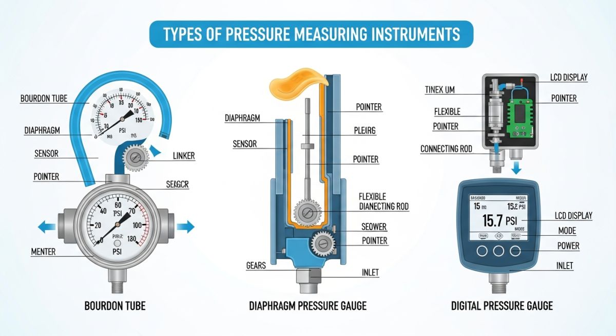
| Bourdon Tube Gauge | C-shaped or Helical Tube | 0.6 bar to 10,000 bar | ASME B40.100 | Susceptible to mechanical vibration |
| Diaphragm Gauge | Corrugated Diaphragm | 10 mbar to 40 bar | EN 837-3 | Lower overpressure limit than Bourdon |
| Bellows Gauge | Thin-walled Metallic Bellows | 1 mbar to 10 bar | ASME B40.100 | Limited to low-pressure applications |
| Piezoelectric Transmitter | Piezoelectric Crystal | 0 to 5,000 bar | ISA 37.3 | Requires continuous electrical power |
How to Verify Pressure Gauge Installations
Before signing off on any mechanical completion package, I personally walk the line to verify the physical installation of every pressure indicator. A poorly supported gauge or a missing isolation valve is an operational hazard waiting to happen. Use this field-tested checklist during your next site walkdown.
Site Walkdown Verification Checklist
-
Isolation Valve Presence: Verify a dedicated block valve (needle or ball valve) is installed directly upstream of the gauge to facilitate safe maintenance and calibration. -
Siphon Installation: Ensure a pigtail or U-type siphon is installed on all steam services to prevent live steam from entering the Bourdon tube. -
Case Liquid Filling: Confirm that gauges installed near pumps, compressors, or high-vibration equipment are liquid-filled (glycerin or silicone) and have their vent plugs snipped. -
Dial Orientation: Verify the dial face is oriented vertically and is clearly visible from the operator access platform or walkway. -
Pressure Rating Match: Cross-reference the gauge’s full-scale range with the piping line class; the operating pressure should ideally fall in the middle 30% to 70% of the dial range. -
Material Traceability: Check the tag or stamping to ensure the wetted parts material matches the piping specification (e.g., 316SS for corrosive process fluids). -
Overpressure Protection: Verify that an overpressure protector or snubber is installed if the system is subject to sudden hydraulic shocks or water hammer.
Field Case Study: Real-World Application
Case Problem: Rapid Gauge Failure in a High-Vibration Slurry Line
At a copper mining processing facility in Chile, the maintenance team reported weekly failures of dry Bourdon tube pressure gauges installed on the discharge manifold of a positive displacement slurry pump. The severe pressure pulsations (ranging from 15 bar to 45 bar at 3 Hz) and intense mechanical vibration caused the pointer needles to snap off, and the internal brass geared movements stripped within days. This left operators blind to line pressure, risking pipeline blockages and pump motor overloads.
Case Outcome: Redesign and Implementation of Diaphragm Seals and Liquid Filling
I was brought in to redesign the instrument hook-up. First, we replaced the dry gauges with glycerin-filled, heavy-duty gauges to damp the high-frequency mechanical vibrations. Second, we isolated the gauge from the abrasive slurry by installing a 316SS flushing-type diaphragm seal filled with high-viscosity silicone oil. Finally, we added a piston-type pressure snubber upstream of the seal to absorb the hydraulic pressure spikes. This configuration completely isolated the delicate internal gears from both physical wear and pressure shocks. The redesigned gauges have now been operating continuously for over 24 months without a single failure, saving the plant thousands in weekly maintenance costs and preventing unplanned downtime.
My direct recommendation for any high-vibration or pulsating service is to never rely on a standard dry gauge. Always specify liquid filling and a mechanical snubber to protect the internal movement mechanism.
Frequently Asked Engineering Questions
What is a Pressure Gauge FAQ Guide
What is the difference between gauge pressure and absolute pressure?
When should I specify a liquid-filled pressure gauge?
How does a diaphragm seal protect a pressure gauge?
What is the purpose of a siphon in steam pressure measurement?
How often should industrial pressure gauges be calibrated?
What are the primary types of pressure measuring instruments?
Complete Course on
Piping Engineering
Check Now
Key Features
- 125+ Hours Content
- 500+ Recorded Lectures
- 20+ Years Exp.
- Lifetime Access
Coverage
- Codes & Standards
- Layouts & Design
- Material Eng.
- Stress Analysis

📚 Recommended Resources: Pressure Measuring Instruments
Related posts:
![Cross-section diagram showing a steel solar pile foundation embedded in layered soil profiles for structural analysis.]()
Essential Geotechnical Pile Design Data for Utility-Scale Solar Structures
![Professional surveyor conducting Topographical Surveys for Solar Projects on a large-scale utility site with complex terrain.]()
Topographical Surveys for Solar Projects: A Technical Engineering Guide
![A geotechnical drill rig performing soil sampling on a large, open field intended for a utility-scale solar farm project.]()
Geotechnical Investigation for Solar Farms: Essential Site Design Guide
![Isometric site plan showing Utility Corridor Planning for Data Centres with color-coded power, water, and telecom infrastructure paths.]()
Utility Corridor Planning for Data Centres: A Strategic Engineering Guide
![Aerial view of a data centre site showcasing perimeter drainage systems, detention basins, and site grading for flood prevention.]()
Drainage Design Considerations for Data Centres: A Technical Guide
![Professional surveyor using a Total Station on a large data centre construction site for topographical mapping.]()
Topographical Surveys for Data Centre Projects: A Technical Guide