
How a Piping Material Engineer Drives Industrial Project Success
In my 20 years of managing piping systems across petrochemical, oil and gas, and power generation facilities, I have seen firsthand how a single incorrect gasket or bolt grade can shut down an entire multi-billion dollar plant. The unsung hero who prevents these catastrophic failures is the Piping Material Engineer. This role requires a deep understanding of metallurgy, corrosion mechanisms, manufacturing standards, and procurement workflows. When I mentor junior engineers, I always emphasize that material selection is not just about reading a table; it is about understanding how a material behaves under extreme pressure, temperature, and corrosive environments over a 30-year design life.
Key Takeaways
- Material selection directly impacts plant safety, mechanical integrity, and lifecycle costs.
- Compliance with ASME B31.3 and ASTM standards is non-negotiable for industrial piping.
- Proper specification prevents catastrophic failures like galvanic corrosion, hydrogen embrittlement, and thermal fatigue.
Complete Course on
Piping Engineering
Check Now
Key Features
- 125+ Hours Content
- 500+ Recorded Lectures
- 20+ Years Exp.
- Lifetime Access
Coverage
- Codes & Standards
- Layouts & Design
- Material Eng.
- Stress Analysis
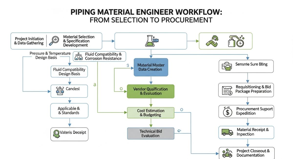
What Does a Piping Material Engineer Do?
Piping Material Specification: The systematic process of compiling technical requirements, pressure-temperature ratings, and material grades into a standardized document that governs procurement and construction under ASME B31.3 guidelines.
The primary responsibility of a Piping Material Engineer is to author the Piping Material Specification (PMS). This document is the bible for any piping project. It defines the pipe class, wall thickness, corrosion allowance, branch connections, and valve types for every fluid service in the plant. To do this effectively, I analyze the process design conditions, including design pressure, design temperature, and fluid composition.
Wall Thickness Calculations
One of the most critical calculations I perform is the pressure design wall thickness of the pipe, governed by ASME B31.3 Section 304.1.2. The formula is written as:
Where:
– t is the pressure design thickness.
– P is the internal design gage pressure.
– D is the outside diameter of the pipe.
– S is the allowable stress value for the material at design temperature (obtained from ASME B31.3 Table A-1).
– E is the quality factor (from Table A-1A or A-1B).
– W is the weld joint strength reduction factor.
– Y is the coefficient value from Table 304.1.1.
Once the design thickness is calculated, I add the corrosion allowance and mechanical tolerances to determine the nominal pipe schedule.
Never substitute ASTM A105 carbon steel flanges for low-temperature service below -29 degrees Celsius without verifying impact test compliance or substituting with ASTM A350 LF2. Doing so risks brittle fracture, which can lead to catastrophic high-pressure gas releases.
Metallurgy and Corrosion Control
In my experience, understanding corrosion is what separates a senior engineer from a junior one. We must design against various degradation mechanisms, including wet H2S damage, sulfidation, chloride stress corrosion cracking (CSCC), and carbonic acid corrosion. For instance, when dealing with wet H2S, I specify NACE MR0175/ISO 15156 compliant materials, which require strict control over hardness limits (typically 22 HRC maximum) and post-weld heat treatment (PWHT).
Why Every Project Needs a Piping Material Engineer
Material Selection Matrix: A structured technical reference mapping fluid services, temperature ranges, and corrosion profiles to specific ASTM material grades to prevent catastrophic mechanical failures.
Without a dedicated engineer managing the material specifications, procurement teams often buy incorrect grades based solely on price. This table outlines the standard material selections I use for common industrial services, ensuring compliance with ASME B31.3.
| Service Fluid | Material Class | ASTM Specification | Temperature Range | ASME B31.3 Stress Ref |
|---|---|---|---|---|
| High-Pressure Steam | Carbon Steel | ASTM A106 Gr. B | -29°C to 427°C | Table A-1 |
| Corrosive Acids | Stainless Steel | ASTM A312 TP316L | -196°C to 538°C | Table A-1 |
| Low-Temp Gas | Low-Temp Carbon Steel | ASTM A333 Gr. 6 | -45°C to 343°C | Table A-1 |
| High-Temp Hydrocarbon | Chrome-Moly Steel | ASTM A335 Gr. P11 | -29°C to 593°C | Table A-1 |
To streamline engineering workflows, I map core technical entities and deliverables to their respective industry standards. This matrix serves as a quick reference for project managers and quality assurance teams.
| Entity / Deliverable | Acronym | Primary Function | Standard Reference |
|---|---|---|---|
| Piping Material Specification | PMS | Defines material classes and pressure ratings | ASME B31.3 |
| Material Take-Off | MTO | Quantifies piping components for procurement | Project Specific |
| Vendor Data Review | VDR | Verifies manufacturer compliance with specs | ASME B16.5 / B16.9 |
| Inspection and Test Plan | ITP | Outlines quality control and testing steps | ISO 9001 / API 570 |
How to Verify Piping Materials on Site
Positive Material Identification: A non-destructive testing method used to verify the chemical composition of alloy piping components on-site to ensure compliance with the Piping Material Specification.
When materials arrive at the construction site, the Piping Material Engineer must ensure that the quality control team performs rigorous checks. I developed this checklist to prevent material mix-ups during the construction phase.
Site Verification Checkpoints
-
Mill Test Reports (MTRs): Verify that all heat numbers stamped on the pipes and fittings match the supplied MTRs. -
PMI Testing: Perform 100% Positive Material Identification on all alloy steel and stainless steel components. -
Flange Face Finish: Inspect flange faces to ensure the surface finish (serrated or smooth) matches ASME B16.5 requirements. -
Marking Verification: Confirm that all components are marked in accordance with MSS SP-25. -
Gasket Dimensions: Verify gasket materials, ratings, and dimensions against ASME B16.20.
Field Case Study: Real-World Application
The Problem
During the commissioning of a high-pressure hydrogen hydrocracker unit, localized cracking was discovered in a 6-inch bypass line. The line was operating at 120 bar and 350°C. A metallurgical analysis revealed that standard carbon steel (ASTM A106 Gr. B) had been installed instead of the specified chromium-molybdenum alloy steel (ASTM A335 Gr. P11). This led to rapid High-Temperature Hydrogen Attack (HTHA), causing micro-fissuring and mechanical failure.
The Outcome
As the lead Piping Material Engineer, I immediately halted commissioning and ordered a 100% PMI sweep of the entire unit. We identified three other misallocated carbon steel spools in high-temperature service. We replaced the affected spools with the correct ASTM A335 Gr. P11 material, performed post-weld heat treatment (PWHT), and implemented a strict “dual-verification” protocol for all alloy piping components prior to welding. This intervention prevented a catastrophic high-pressure hydrogen release and fire.
My direct recommendation for any high-pressure, high-temperature project is to mandate 100% PMI at the fabrication shop and again at the job site prior to installation. Never rely solely on paper MTRs.
Frequently Asked Engineering Questions
What is the difference between ASTM A106 Grade B and ASTM A53 Grade B?
How does a Piping Material Engineer determine the corrosion allowance?
When is impact testing required for piping materials?
What is the role of a Piping Material Engineer during the procurement phase?
How do you prevent galvanic corrosion in mixed-metal piping systems?
What is the significance of the Carbon Equivalent (CE) in piping materials?
===