Table of Contents
Understanding Piping vs Pipeline Wall Thickness Calculation Differences
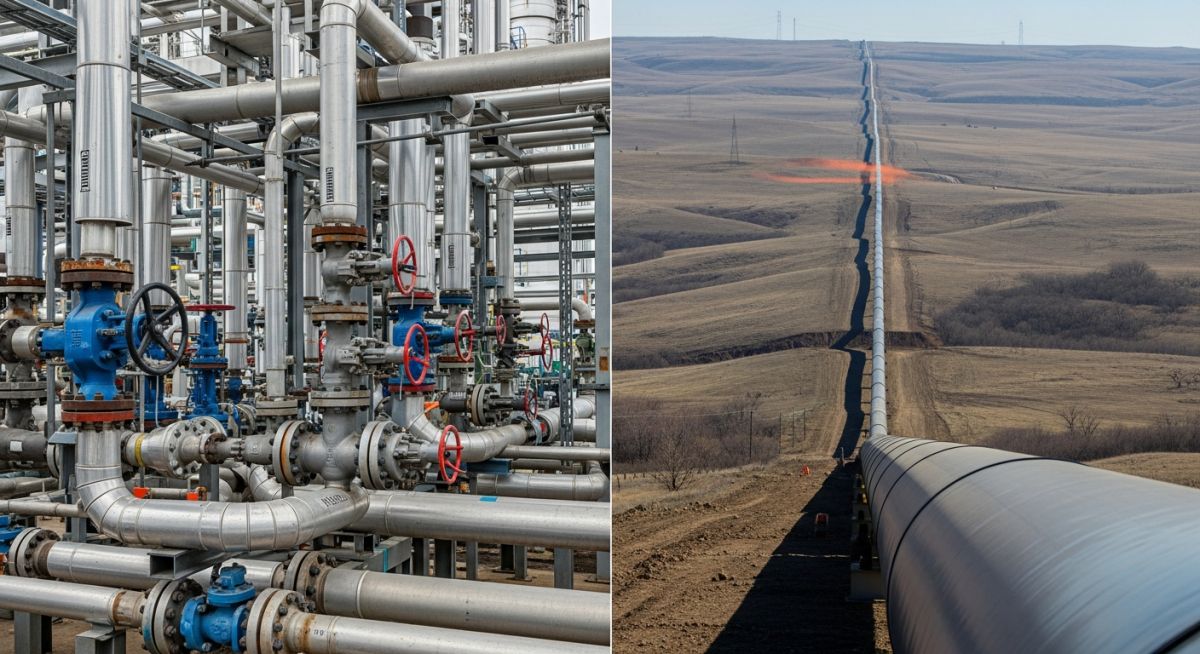
In my 20 years of managing piping and pipeline engineering projects, I have seen many young engineers stumble when transitioning from plant piping design to cross-country pipeline engineering. The math looks similar on the surface, but the underlying safety philosophies are worlds apart. Plant piping operates in highly congested environments with high-temperature thermal cycles, while pipelines stretch across hundreds of miles of varying terrain, facing soil loads, environmental hazards, and transient pressure surges.
Understanding the nuances of piping vs pipeline wall thickness is not just an academic exercise; it is a critical safety and financial requirement. Over-designing a 100-mile pipeline by even 1 millimeter of wall thickness can inflate project steel costs by millions of dollars. Conversely, under-designing plant piping by ignoring mill tolerances or corrosion allowances can lead to catastrophic, high-energy piping failures.
Key Engineering Takeaways
- Code Boundaries: Plant piping is governed by ASME B31.3, while liquid pipelines follow ASME B31.4 and gas pipelines follow ASME B31.8.
- Design Factors: Pipelines use a variable design factor (F) based on location class, whereas piping uses a fixed allowable stress based on material tensile properties.
- Corrosion & Mill Tolerances: ASME B31.3 strictly requires adding corrosion allowance and a 12.5% mill tolerance to the calculated minimum thickness, whereas pipeline codes handle these parameters differently due to active cathodic protection.
- Stress Limits: Pipeline codes allow higher stress levels (up to 72% or 80% of SMYS) compared to the more conservative limits in process piping (typically around 33% of tensile strength).
Key Differences in Piping vs Pipeline Wall Thickness
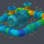
Wall Thickness Design Philosophy: Piping systems are designed for high-temperature, high-cyclic thermal stresses within compact plant boundaries, while pipelines are optimized for long-distance fluid transport across varying terrains with transient pressure surges.
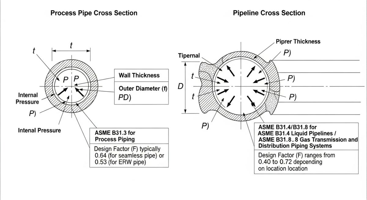
To understand the differences, we must look at the primary equations used to calculate the pressure design thickness. In process piping, the ASME B31.3 formula for determining the minimum required wall thickness (t) of a straight pipe under internal pressure is:
Where:
P = Internal design gage pressure.
D = Outside diameter of the pipe.
S = Allowable stress value for the material at design temperature.
E = Quality factor (longitudinal weld joint factor).
W = Weld joint strength reduction factor (used at high temperatures).
Y = Coefficient from Table 304.1.1, which accounts for material ductility and temperature.
Now, let us compare this to the pipeline design formula. For liquid transportation pipelines under ASME B31.4, and gas transmission pipelines under ASME B31.8, the nominal wall thickness (t) is calculated using a modified version of Barlow’s Formula:
Where:
P = Internal design pressure.
D = Outside diameter of the pipe.
S = Specified Minimum Yield Strength (SMYS) of the pipe material.
F = Design factor (ranges from 0.40 to 0.72 or 0.80, depending on location class and risk).
E = Longitudinal joint factor.
T = Temperature derating factor (typically 1.0 for temperatures below 250°F / 121°C).
The Role of Location Classes in Pipeline Design
One of the most significant differences in pipeline design is the introduction of the Location Class. Under ASME B31.8 (Gas Transmission), the design factor (F) decreases as the population density near the pipeline increases.
For instance, in Class 1 locations (desert or farmland with few buildings), the design factor is 0.72, allowing the pipeline to operate at up to 72% of its yield strength. In Class 4 locations (densely populated urban areas with multi-story buildings), the design factor drops to 0.40, requiring a much thicker pipe wall to mitigate the consequences of a potential failure. Plant piping under ASME B31.3 does not use location classes; it maintains a consistently high safety margin regardless of where the plant is built.
| Design Parameter | ASME B31.3 (Process Piping) | ASME B31.4 (Liquid Pipeline) | ASME B31.8 (Gas Pipeline) |
|---|---|---|---|
| Primary Governing Code | Process Piping inside plant battery limits | Liquid transportation systems outside plants | Gas transmission and distribution systems |
| Allowable Stress Basis | Lower of 1/3 Tensile Strength or 2/3 Yield Strength | Based on Specified Minimum Yield Strength (SMYS) | Based on Specified Minimum Yield Strength (SMYS) |
| Design Factor (F) | Not applicable (built into allowable stress) | Typically 0.72 (up to 0.80 for specific cases) | Variable (0.40, 0.50, 0.60, or 0.72) based on Class |
| Mill Tolerance (12.5%) | Mandatory addition to calculated thickness | Not added directly to design thickness equation | Not added directly to design thickness equation |
| Corrosion Allowance | Explicitly added based on fluid corrosivity | Managed via cathodic protection and inhibitors | Managed via cathodic protection and dry gas specs |
| Entity / Acronym | Physical Parameter | Standard Reference | Engineering Application |
|---|---|---|---|
| SMYS | Yield Strength (psi or MPa) | API Spec 5L | Defines the minimum stress at which steel permanently deforms. |
| Mill Tolerance | Under-thickness percentage (12.5%) | ASME B36.10M | Accounts for manufacturing variations in seamless and welded pipe. |
| Location Class | Population density index (1 to 4) | ASME B31.8 | Determines the design factor (F) to ensure safety in populated areas. |
| Joint Efficiency (E) | Weld quality factor (0.60 to 1.00) | ASME B31.3 Table 302.3.4 | Reduces allowable stress based on the type of weld and inspection level. |
Calculating Piping vs Pipeline Wall Thickness Safely
Wall Thickness Verification: Field engineers must verify nominal wall thickness against calculated minimum thickness by accounting for mill tolerance, corrosion allowance, and mechanical thread depth before releasing piping isometrics for fabrication.
When you are on-site or reviewing engineering drawings, you cannot rely solely on the theoretical output of a software package. I always insist that my team performs a manual sanity check using this structured verification process.
Step-by-Step Wall Thickness Verification Checklist
Field Case Study: Real-World Application
The Problem: Over-Designed Off-Site Transfer Line
During a major refinery expansion project in the Middle East, a junior engineering contractor designed a 12-mile, 24-inch crude oil transfer line running from the refinery to a marine terminal. Because the line originated inside the refinery, the engineer applied ASME B31.3 process piping rules to the entire 12-mile length.
This resulted in a calculated wall thickness of 12.7 mm (Schedule 40), incorporating a heavy corrosion allowance and a 12.5% mill tolerance. The procurement cost for this heavy-wall pipe threatened to push the project significantly over budget.
The Outcome: Code Re-Classification and Optimization
When I was brought in to review the design, I immediately identified that the off-site portion of the line (outside the refinery fence) fell under the jurisdiction of ASME B31.4 for liquid transportation. By re-calculating the wall thickness using the ASME B31.4 formula with a design factor of 0.72 and utilizing high-strength API 5L X65 pipe, we safely reduced the required wall thickness to 8.2 mm.
This change reduced the total steel tonnage by over 30%, saving the client approximately 1.4 million in material costs and significantly reducing welding time in the field. The design remained fully compliant with local regulations and international safety standards.
This case highlights why understanding the boundary limits between plant piping and cross-country pipelines is so important. A simple misunderstanding of code applicability can lead to massive financial waste without adding any real-world safety benefits.
Frequently Asked Engineering Questions
Why does ASME B31.3 require a mill tolerance addition while ASME B31.4/B31.8 does not?
Can I use API 5L line pipe for plant piping under ASME B31.3?
How does corrosion allowance differ between piping and pipelines?
What is the significance of the design factor (F) in ASME B31.8?
Can a pipeline code be used inside a refinery or chemical plant?
How do temperature limits affect wall thickness calculations in these codes?
===FAQ_BLOCK===
Complete Course on
Piping Engineering
Check Now
Key Features
- 125+ Hours Content
- 500+ Recorded Lectures
- 20+ Years Exp.
- Lifetime Access
Coverage
- Codes & Standards
- Layouts & Design
- Material Eng.
- Stress Analysis

📚 Recommended Resources: piping vs pipeline wall thickness
Read these Guides


Related posts:
![Infographic flowchart of the GRP GRE FRP piping stress analysis workflow in START-PROF.]()
Rigid Struts: Definition, Applications, and Modeling in Caesar II
![3D stress analysis model of GRP piping system in START-PROF software showing stress distribution.]()
Stress Analysis of GRP / GRE / FRP Piping using START-PROF
![Industrial centrifugal pump installed on a concrete foundation with precision piping and alignment.]()
How to Use a Pump Installation Checklist for Maximum Reliability
![3D Caesar II pipe stress analysis model of a centrifugal pump piping system showing stress distribution.]()
Pump-Piping Alignment Caesar II Stress Analysis Methodology
![3D render of a structural steel cross-bracing connection with a gusset plate.]()
Mastering Steel Connections with a Cross-Bracing Design Example
![Industrial engineer checking shaft alignment on a centrifugal pump during commissioning.]()
How to Use a Pump Commissioning Checklist for Start-Up