Mastering the Piping Material Specification for Industrial Plant Design
In my 20 plus years of managing piping engineering teams for mega-scale petrochemical and oil refineries, I have seen projects succeed or fail based on a single document: the piping material specification (PMS). I remember a specific offshore platform project in the North Sea where a minor discrepancy in the PMS led to the procurement of standard carbon steel valves instead of duplex stainless steel for a high-chloride service. The resulting delay cost the operator millions. This document is not just a collection of tables; it is the legal and technical backbone of your entire piping system.
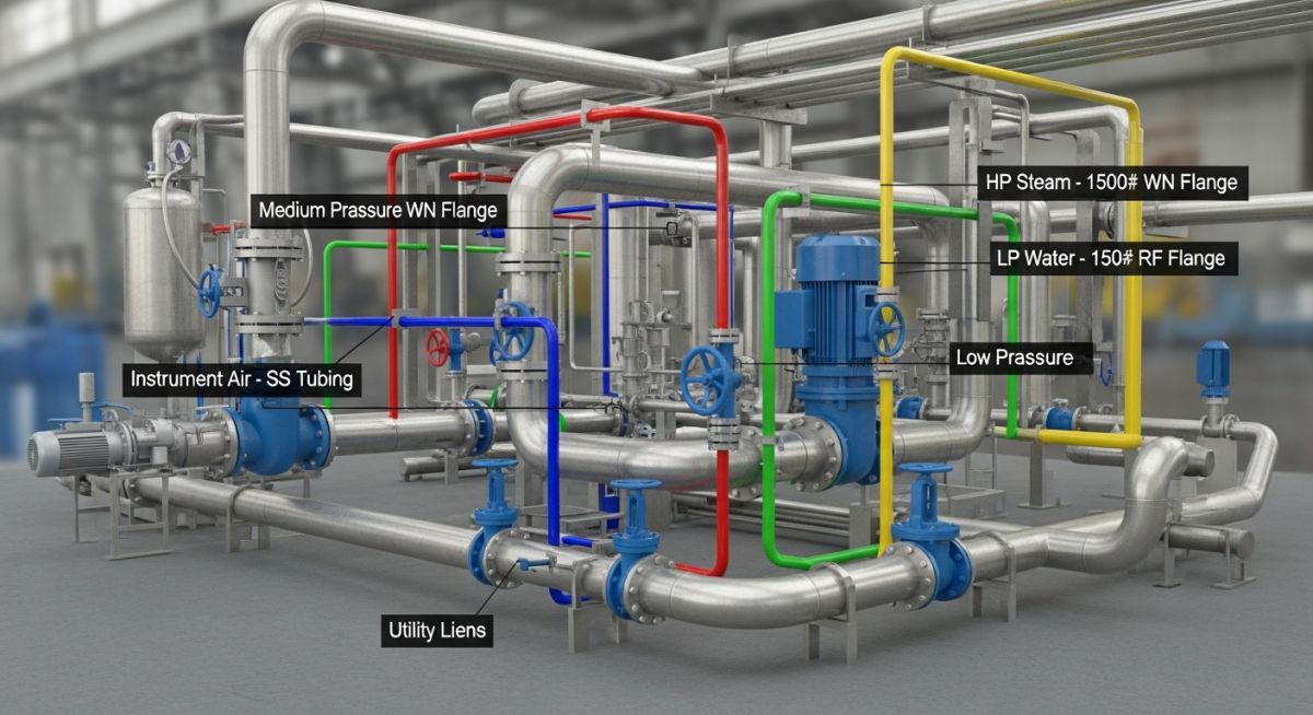
When we design a process plant, we deal with hundreds of different fluids, ranging from highly corrosive acids to high-pressure steam. It is physically and economically impossible to design a unique piping system for every single line. Instead, we group similar process conditions into standardized “Piping Classes.” The PMS is the master compilation of these classes, detailing exactly which pipe, flange, fitting, gasket, and valve can be safely used for any given service.
Key Takeaways of a PMS
- Standardizes material selection across the entire asset lifecycle.
- Ensures strict compliance with ASME B31.3, ASME B16.5, and API standards.
- Minimizes procurement errors and streamlines field fabrication.
- Optimizes wall thickness calculations to prevent catastrophic failures.
- Provides clear guidelines for non-destructive testing (NDT) and post-weld heat treatment (PWHT).
Why is a Piping Material Specification Necessary?
A robust PMS eliminates ambiguity. It translates complex code requirements from ASME B31.3 Process Piping into a highly structured, easy-to-use format for designers, purchasing agents, and field inspectors. Without a PMS, a designer might select a pipe wall thickness that is too thin for the operating pressure, or a purchasing agent might buy a flange with an incompatible pressure rating.
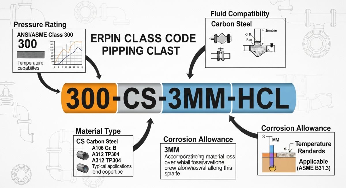
Each piping class within a PMS is designated by a unique alphanumeric code. In my practice, I prefer a three-character coding system that instantly tells the engineer the pressure rating, material, and corrosion allowance. For example, in the class code A1A:
- First Character (A): Represents the ASME flange rating class. “A” stands for Class 150, “B” for Class 300, “D” for Class 600, and “E” for Class 900.
- Second Character (1): Represents the material group. “1” stands for Carbon Steel, “2” for Alloy Steel, “3” for Stainless Steel, and “4” for Nickel Alloys.
- Third Character (A): Represents the corrosion allowance and service type. “A” might denote a 1.5 mm corrosion allowance for non-corrosive service, while “B” denotes a 3.0 mm corrosion allowance for corrosive service.
The Mathematics of Wall Thickness Selection
The core engineering calculation behind any piping class is the determination of the minimum required pipe wall thickness. Under ASME B31.3 Section 304.1.2, the pressure design thickness (t) for straight pipe under internal pressure is calculated using the following formula:
Where:
- P = Internal design gage pressure (psi or MPa)
- D = Outside diameter of the pipe (inches or mm)
- S = Allowable stress value for the material at design temperature from ASME B31.3 Table A-1 (psi or MPa)
- E = Quality factor from ASME B31.3 Table A-1A or A-1B
- W = Weld joint strength reduction factor
- Y = Coefficient from ASME B31.3 Table 304.1.1
Once the pressure design thickness (t) is calculated, we must add the mechanical allowances (such as thread depth or groove depth, “a”) and the corrosion/erosion allowance (c) to find the minimum required thickness ™:
Finally, because commercial pipes are manufactured with a mill tolerance (typically minus 12.5% for seamless pipe), the nominal pipe wall thickness (tn) selected from ASME B36.10M must satisfy:
Standard Piping Class Pressure Temperature Ratings
The table below outlines the maximum allowable working pressures (in psig) for standard carbon steel piping components (ASTM A105/A106 Gr. B) across various ASME flange classes, in accordance with ASME B16.5 Group 1.1 materials.
| Temperature (°F) | Class 150 (psig) | Class 300 (psig) | Class 600 (psig) | Class 900 (psig) |
|---|---|---|---|---|
| -20 to 100 | 285 | 740 | 1480 | 2220 |
| 200 | 260 | 680 | 1360 | 2035 |
| 400 | 200 | 615 | 1230 | 1845 |
| 600 | 140 | 570 | 1135 | 1705 |
| 800 | 80 | 410 | 825 | 1235 |
Technical Mapping & Specifications Matrix
To maintain absolute clarity across engineering disciplines, the following matrix maps core technical entities, structural acronyms, and physical parameters to their primary standard references.
| Entity / Acronym | Technical Definition | Primary Standard Reference | Field Application |
|---|---|---|---|
| PMS | Piping Material Specification | ASME B31.3 | Master procurement and design document. |
| Piping Class | Specific pressure-temperature-material grouping | ASME B16.5 | Standardizes components for specific process lines. |
| NPS | Nominal Pipe Size (dimensionless designator) | ASME B36.10M | Defines physical outer diameter of piping. |
| Schedule (SCH) | Pipe wall thickness designation | ASME B36.19M | Determines pressure containment capability. |
| CA | Corrosion Allowance (sacrificial thickness) | NACE MR0175 / API 571 | Protects pipe wall from chemical degradation. |
Verifying Materials Against the Piping Material Specification
In the field, quality control is your last line of defense. I have established a rigorous verification protocol on my construction sites to ensure that no non-compliant materials are welded into the system. This checklist must be executed by the Lead Piping Inspector prior to releasing any spool for fabrication.
Pre-Fabrication Material Verification Checklist
-
Verify Physical Pipe Markings: Cross-reference the physical stencil on the pipe (ASTM grade, heat number, size, schedule) directly with the approved PMS class.
-
Review Mill Test Reports (MTRs): Confirm that the chemical composition and mechanical properties on the MTR comply with ASME Section II material standards.
-
Inspect Flange Face Finish: Ensure the flange serrations (e.g., 125 to 250 AARH) match the specific gasket requirements defined in the PMS class.
-
Validate Bolting Materials: Confirm that the stud bolts (e.g., ASTM A193 Gr. B7) and nuts (e.g., ASTM A194 Gr. 2H) match the specified class and are free of surface defects.
-
Perform Positive Material Identification (PMI): Execute 100% PMI testing on all alloy and stainless steel components to verify chemical composition before welding.
-
Check Gasket Dimensions and Material: Verify that spiral wound gaskets have the correct outer ring, inner ring, and filler material (e.g., 316SS with Graphite) as specified.
-
Confirm Valve Orientation and Trim: Ensure that check valves and control valves are oriented correctly according to flow direction, and that the valve trim matches the PMS datasheet.
Field Case Study: Real-World Application
The Problem: High-Temperature Hydrogen Attack (HTHA)
During a major refinery turnaround, a mechanical contractor substituted standard carbon steel (ASTM A106 Gr. B) pipe for a 1.25Cr-0.5Mo alloy steel (ASTM A335 Gr. P11) line in high-temperature hydrogen service operating at 650°F and 450 psig. The mistake occurred because the piping class code on the isometric drawing was misread. Within six months of operation, the line experienced severe High-Temperature Hydrogen Attack (HTHA), leading to localized decarburization, micro-cracking, and a major pinhole leak that triggered an emergency plant shutdown.
The Outcome: Root Cause Analysis & Rectification
I was called in to lead the root cause analysis. We immediately isolated the line and performed ultrasonic testing (UT) to map the extent of the damage. The entire run was replaced with the correct ASTM A335 Gr. P11 material as specified in the PMS. To prevent recurrence, we implemented a mandatory 100% Positive Material Identification (PMI) protocol for all alloy piping systems prior to welding, and updated the digital isometric templates to display the piping class in high-contrast, bold fonts. The plant resumed operations safely, and subsequent inspections showed zero degradation.
This incident highlights the absolute necessity of strict adherence to the piping material specification. A simple material mix-up can lead to catastrophic failures, environmental hazards, and massive financial losses.
Frequently Asked Engineering Questions
What is the difference between a piping specification and a piping class?
How do you select the corrosion allowance for a piping class?
Can I substitute a higher-grade material than what is specified in the PMS?
What does the term “AARH” mean in flange specifications?
How does ASME B31.3 define the temperature limits for carbon steel?
Why do some piping classes require Post-Weld Heat Treatment (PWHT)?
===FAQ_BLOCK===
Complete Course on
Piping Engineering
Check Now
Key Features
- 125+ Hours Content
- 500+ Recorded Lectures
- 20+ Years Exp.
- Lifetime Access
Coverage
- Codes & Standards
- Layouts & Design
- Material Eng.
- Stress Analysis

📚 Recommended Resources: piping material specification
Read these Guides
🎓 Advanced Training


Related posts:
![Cross-section diagram showing a steel solar pile foundation embedded in layered soil profiles for structural analysis.]()
Essential Geotechnical Pile Design Data for Utility-Scale Solar Structures
![Professional surveyor conducting Topographical Surveys for Solar Projects on a large-scale utility site with complex terrain.]()
Topographical Surveys for Solar Projects: A Technical Engineering Guide
![A geotechnical drill rig performing soil sampling on a large, open field intended for a utility-scale solar farm project.]()
Geotechnical Investigation for Solar Farms: Essential Site Design Guide
![Isometric site plan showing Utility Corridor Planning for Data Centres with color-coded power, water, and telecom infrastructure paths.]()
Utility Corridor Planning for Data Centres: A Strategic Engineering Guide
![Aerial view of a data centre site showcasing perimeter drainage systems, detention basins, and site grading for flood prevention.]()
Drainage Design Considerations for Data Centres: A Technical Guide
![Professional surveyor using a Total Station on a large data centre construction site for topographical mapping.]()
Topographical Surveys for Data Centre Projects: A Technical Guide