What is a Ball Valve? Design, Types, and Engineering Standards
In my 20 plus years of designing piping systems for oil refineries and chemical processing plants, I have specified thousands of isolation valves. Among them, the ball valve remains the absolute workhorse of modern process industries. When you need tight shut-off, rapid operation, and minimal pressure drop, nothing matches the reliability of a properly engineered quarter-turn spherical valve.
However, selecting the wrong configuration can lead to catastrophic seat degradation, stem leakage, or actuator failure. In this guide, I will share my practical field experience and the deep technical parameters you must evaluate to ensure your valve selections perform flawlessly under extreme industrial conditions.
Key Engineering Takeaways
- Understand the structural differences between floating and trunnion-mounted designs.
- Master the torque calculations required for accurate actuator sizing.
- Identify the correct seat and seal materials based on process temperature and fluid chemistry.
- Navigate the critical testing standards including API 598 and API 6D.
How Does a Ball Valve Control Flow?
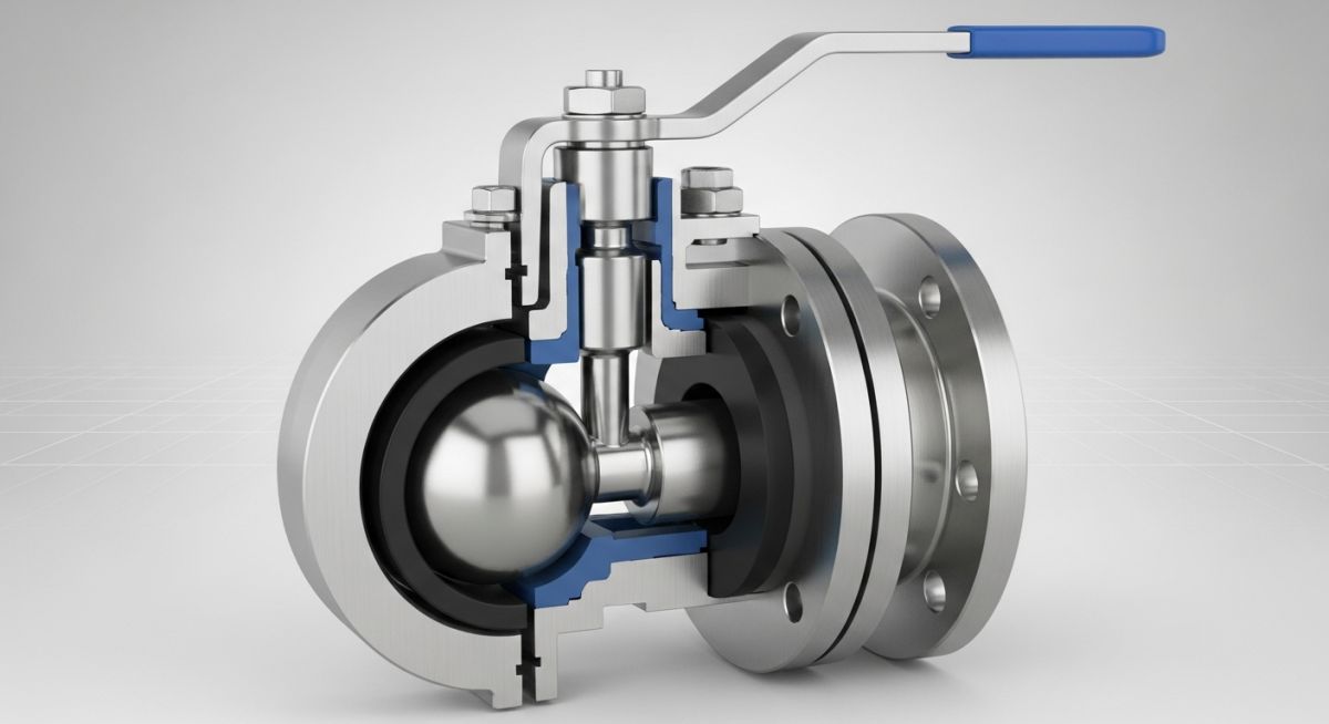
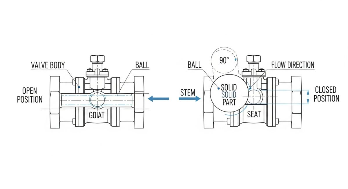
The fundamental operating principle of a ball valve relies on a rotary stem turning a spherical ball with a hollow bore. When the bore aligns with the pipeline, fluid passes through with minimal resistance. Rotating the stem by 90 degrees positions the solid face of the ball perpendicular to the flow path, completely blocking the fluid.
Floating vs. Trunnion-Mounted Designs
In a floating ball valve, the ball is suspended between two elastomeric or thermoplastic seats. The upstream fluid pressure physically pushes the ball against the downstream seat, enhancing the sealing force. This design is highly effective for low to medium pressure classes (up to ASME Class 300) and smaller line sizes. However, at high pressures or large diameters, the force exerted on the downstream seat becomes excessive, leading to high operating torque and accelerated seat wear.
For high-pressure services (ASME Class 600 and above) or larger line sizes (typically 6 inches and larger), a trunnion-mounted ball valve is mandatory. Here, the ball is anchored by a shaft at the bottom (the trunnion) and the stem at the top. The ball remains stationary, and the fluid pressure forces spring-loaded, floating seat rings against the ball. This dramatically reduces operating torque and distributes mechanical loads evenly, protecting the internal components from premature failure.
Engineering Torque Calculations
To size an actuator correctly, you must calculate the total operating torque. The total torque (Tt) is a function of seat friction, stem packing friction, and bearing friction:
Where:
Ts = Seat friction torque = D * A * dP * f
Tp = Stem packing friction torque
Tb = Bearing friction torque (for trunnion designs)
D = Mean diameter of the seat seal
A = Area of the ball port
dP = Maximum differential pressure across the valve
f = Friction coefficient of the seat material (e.g., 0.05 for PTFE, 0.25 for metal-to-metal)
Always apply a safety factor of at least 1.3 to 1.5 to the calculated torque when sizing pneumatic or electric actuators to account for service degradation, dry run conditions, and breakaway torque requirements.
Selecting the Right Ball Valve Materials
Selecting the correct materials for the body, ball, stem, and seats is the most critical step in ensuring long-term valve integrity. For standard hydrocarbon service, carbon steel ASTM A105 (forged) or ASTM A216 WCB (cast) is the industry standard. For corrosive or low-temperature services, stainless steel ASTM A182 F316 or ASTM A351 CF8M is specified.
Seat materials dictate the temperature and pressure limits of the valve. Soft seats made of PTFE, Reinforced PTFE (RPTFE), or Devlon offer bubble-tight shut-off but are limited to temperatures below 200 degrees Celsius. For high-temperature or abrasive slurry services, metal-to-metal seats with tungsten carbide or chromium carbide coatings must be utilized in accordance with ASME B16.34.
The table below outlines the maximum allowable working pressures (in bar) for common valve body materials across various ASME pressure classes at standard operating temperatures, compiled from ASME B16.34.
| Material Spec | Temp (°C) | Class 150 (bar) | Class 300 (bar) | Class 600 (bar) | Class 900 (bar) |
|---|---|---|---|---|---|
| ASTM A105 / WCB | -29 to 38 | 19.6 | 51.1 | 102.1 | 153.2 |
| ASTM A105 / WCB | 100 | 17.7 | 46.6 | 93.2 | 139.7 |
| ASTM A182 F316 / CF8M | -29 to 38 | 19.0 | 49.6 | 99.3 | 148.9 |
| ASTM A182 F316 / CF8M | 150 | 15.8 | 41.4 | 82.7 | 124.1 |
This matrix maps the core components of industrial ball valves to their typical material grades, design standards, and primary engineering functions.
| Component | Common Acronym | Standard Materials | Design Standard | Primary Function |
|---|---|---|---|---|
| Valve Body | BDY | A105, WCB, LCC, F316 | ASME B16.34 | Pressure containment and piping connection |
| Spherical Ball | BAL | F316, 17-4PH, Duplex | API 6D | Flow isolation and path control |
| Valve Seats | SEA | PTFE, RPTFE, Devlon, PEEK | API 6D | Bubble-tight sealing interface |
| Stem Packing | PKG | Graphite, PTFE V-rings | API 622 / API 641 | Fugitive emission prevention |
Site Verification Checklist for Valve Installation
Before commissioning any newly installed ball valve, field engineers must execute a rigorous inspection. Skipping these steps often results in damaged seats, stem leaks, or actuator binding during initial startup.
Pre-Commissioning Inspection Protocol
-
Flow Direction & Orientation: Verify that the valve is installed in the correct orientation, especially for unidirectional designs or valves with preferred sealing directions.
-
Flange Alignment & Parallelism: Ensure mating flanges are aligned within the tolerances specified by ASME B31.3 to prevent bending stresses on the valve body.
-
Bolt Torque Verification: Confirm that flange bolting has been tightened in a star pattern sequence using calibrated torque wrenches to the specified torque values.
-
Actuator Limit Switch Calibration: Verify that the actuator fully opens and fully closes the valve. Misaligned limit switches can leave the ball slightly open, causing high-velocity seat erosion.
-
Cavity Relief Check: For double-seated valves in liquid service, verify that the cavity relief system is functional to prevent thermal overpressurization of the valve body cavity.
Field Case Study: Real-World Application
The Problem: Severe Seat Bypass in Wet Gas Service
At a natural gas processing facility, a 12-inch Class 600 floating ball valve with RPTFE seats was experiencing severe bypass leakage within six months of installation. The process fluid contained wet natural gas with entrained sand particles. The high operating torque had also caused the pneumatic actuator to stall during emergency shutdown (ESD) testing.
The Outcome: Redesign and Material Upgrade
I led the engineering investigation and identified two primary failure modes: particulate entrapment behind the floating ball seats and excessive seat load due to high differential pressure. We replaced the valve with a trunnion-mounted ball valve featuring metal-to-metal seats (tungsten carbide coated) and a double block and bleed (DBB) configuration.
The trunnion design reduced the operating torque by 45 percent, allowing the existing actuator to operate smoothly. The metal seats successfully resisted the abrasive sand particles, and the valve has now operated for over four years without any measurable bypass leakage.
Direct Recommendation: Always specify trunnion-mounted designs with metal-to-metal seats when handling fluids containing particulates or when operating in pressure classes above Class 300 in lines larger than 6 inches.
Frequently Asked Engineering Questions
What is the difference between full bore and reduced bore ball valves?
Why is cavity pressure relief necessary in ball valves?
What is a Double Block and Bleed (DBB) valve?
How does API 6D differ from API 598 testing?
What is an anti-static device in a ball valve?
When should I specify metal-seated ball valves?
===
Complete Course on
Piping Engineering
Check Now
Key Features
- 125+ Hours Content
- 500+ Recorded Lectures
- 20+ Years Exp.
- Lifetime Access
Coverage
- Codes & Standards
- Layouts & Design
- Material Eng.
- Stress Analysis

📚 Recommended Resources: ball valve
Read these Guides
🎓 Advanced Training


Related posts:
![Cross-section diagram showing a steel solar pile foundation embedded in layered soil profiles for structural analysis.]()
Essential Geotechnical Pile Design Data for Utility-Scale Solar Structures
![Professional surveyor conducting Topographical Surveys for Solar Projects on a large-scale utility site with complex terrain.]()
Topographical Surveys for Solar Projects: A Technical Engineering Guide
![A geotechnical drill rig performing soil sampling on a large, open field intended for a utility-scale solar farm project.]()
Geotechnical Investigation for Solar Farms: Essential Site Design Guide
![Isometric site plan showing Utility Corridor Planning for Data Centres with color-coded power, water, and telecom infrastructure paths.]()
Utility Corridor Planning for Data Centres: A Strategic Engineering Guide
![Aerial view of a data centre site showcasing perimeter drainage systems, detention basins, and site grading for flood prevention.]()
Drainage Design Considerations for Data Centres: A Technical Guide
![Professional surveyor using a Total Station on a large data centre construction site for topographical mapping.]()
Topographical Surveys for Data Centre Projects: A Technical Guide