Topographical Surveys for Solar Projects: A Technical Guide
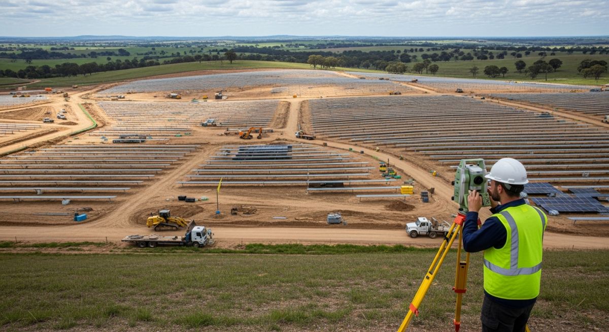
In my two decades of experience managing utility-scale energy projects, I have learned that the success of a solar farm is often determined long before the first pile is driven. A high-fidelity topographical survey is the bedrock of this process. Without accurate terrain data, you risk significant cost overruns during the civil works phase, particularly regarding earthwork balancing and stormwater management.
I approach every site by prioritizing the integration of Digital Terrain Models (DTM) with geotechnical data. This synergy allows us to predict potential shading issues caused by undulating terrain and ensures that our racking systems are designed for the actual site slope rather than theoretical flat-plane assumptions.
Key Takeaways for Project Success:
- Achieve precise earthwork volume calculations to minimize site grading costs.
- Identify critical drainage paths to prevent erosion and structural foundation failure.
- Utilize high-density LiDAR or RTK-GPS data for accurate shading analysis.
- Ensure compliance with local civil engineering codes and environmental permitting requirements.
Technical Analysis of Topographical Surveys for Solar Projects
Topographical Surveys for Solar Projects: These surveys involve the systematic collection of geodetic data to create a high-resolution representation of the site, enabling precise civil design and structural optimization.
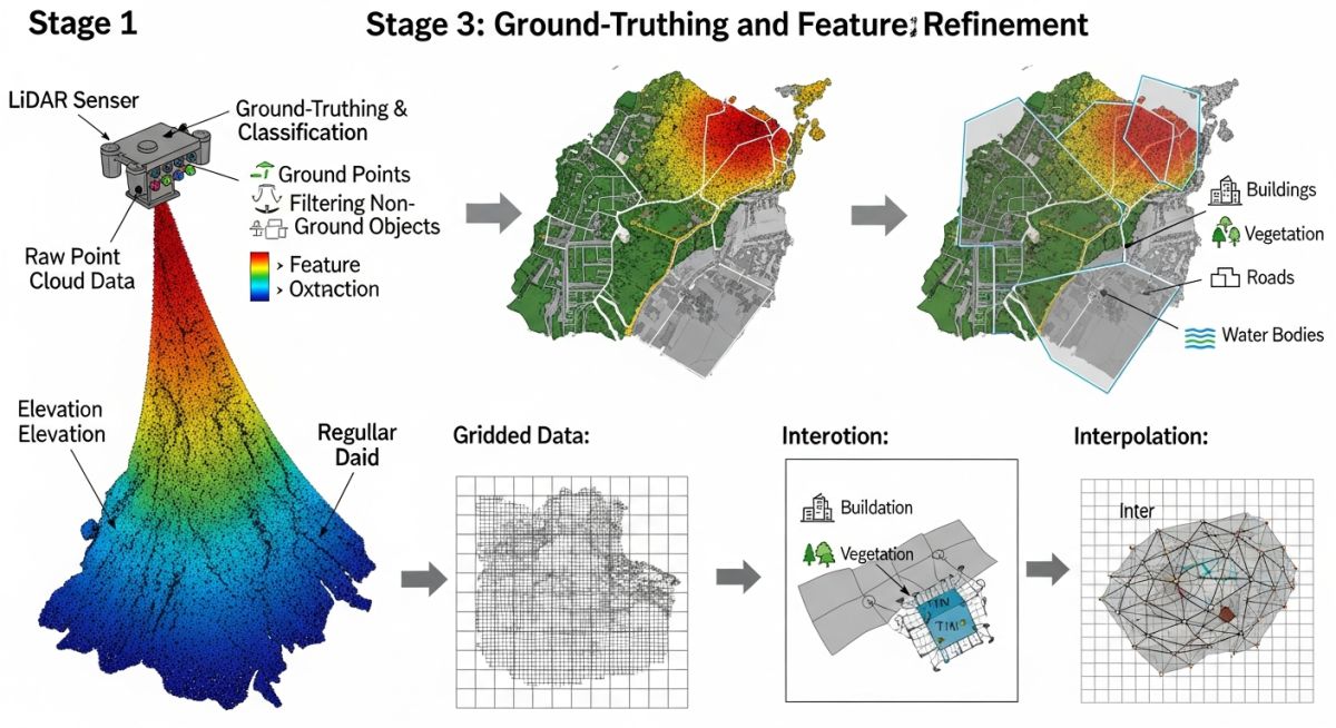
When I oversee a site survey, I mandate a minimum point density that accounts for the specific racking technology being deployed. For single-axis trackers, the tolerance for slope variation is significantly tighter than for fixed-tilt systems. We typically utilize Real-Time Kinematic (RTK) GPS combined with drone-based LiDAR to capture the ground surface, effectively filtering out vegetation to generate a true bare-earth DTM.
Terrain Analysis and DTM Generation
The DTM is the primary input for our civil design software. We calculate the slope percentage using the formula: Slope = (Rise / Run) * 100. For solar projects, we aim to keep the grading footprint minimal. If the slope exceeds 10-15%, we must evaluate the structural impact on the tracker drive systems, as excessive slope can lead to binding or increased torque requirements on the motor.
Field Warning: Data Interpolation Risks
Never rely on low-resolution public elevation data (like SRTM) for final design. These datasets often fail to capture small-scale terrain features that cause significant shading or drainage issues. Always perform a site-specific survey with a vertical accuracy of at least 50mm to ensure the structural integrity of the racking foundations.
Drainage and Shading Assessment
Drainage assessment is not just about water flow; it is about protecting the electrical infrastructure. I have seen projects where poor drainage mapping led to the flooding of inverter pads. We use the survey data to model 10-year and 100-year storm events, ensuring that the site grading directs water away from sensitive equipment.
Shading analysis requires the survey to capture not only the ground but also peripheral features like tree lines, existing buildings, and power lines. By importing the survey coordinates into software like PVSyst, we can simulate the sun’s path throughout the year, identifying potential losses that could impact the project’s internal rate of return (IRR).
Survey Methodology Trade-offs: Evaluating the technical benefits and operational limitations of high-precision topographical data collection methods in utility-scale solar development.
Advantages
- Reduces civil earthwork costs by enabling precise cut-and-fill volume calculations.
- Mitigates long-term structural risks by identifying unstable soil or drainage-prone areas.
- Improves energy yield accuracy by providing precise shading profiles for tracker optimization.
- Accelerates the permitting process by providing high-quality, defensible site documentation.
Disadvantages
- High initial capital expenditure for professional-grade LiDAR and RTK-GPS equipment.
- Requires significant time for data processing and cleaning of point clouds.
- Susceptibility to errors if ground control points are not properly established.
- Potential for data obsolescence if significant site clearing occurs after the survey.
Topographical Survey Implementation: Applying precise spatial data across diverse project environments to ensure structural and operational compliance.
Utility-Scale Tracker Optimization
High-precision surveys are vital for single-axis tracker projects where the mechanical drive system is sensitive to slope variations. By mapping the terrain in 3D, we can adjust the pile lengths and tracker row spacing to prevent mechanical binding and maximize the tracking range of motion.
Brownfield Site Redevelopment
When converting former industrial sites to solar farms, topographical surveys help identify legacy foundations and uneven ground settlement. This data is critical for designing foundation systems that avoid subsurface obstructions while ensuring the site remains properly graded for environmental containment.
Stormwater Management Design
In regions with strict environmental regulations, the survey data serves as the basis for hydraulic modeling. We use the DTM to design swales, retention ponds, and drainage channels that prevent erosion around the solar array, ensuring the site meets local civil engineering standards for runoff control.
When executing large-scale solar developments, the precision of your topographical data dictates the viability of the entire racking and mounting system. In my two decades of experience, I have observed that failing to align survey accuracy with the specific requirements of the mounting technology—whether fixed-tilt or single-axis tracker—leads to significant cost overruns during the construction phase. The following table outlines the industry-standard tolerances required for various stages of site development, ensuring that your Digital Terrain Model (DTM) provides a reliable foundation for civil and structural design.
These values are derived from standard ASCE guidelines for land development and NREL best practices for utility-scale solar. Note that for single-axis trackers, the vertical tolerance is significantly tighter than for fixed-tilt systems due to the sensitivity of the drive mechanism to ground slope variations. Always verify these requirements against the specific manufacturer’s installation manual before finalizing your survey scope of work.
| Survey Parameter | Fixed-Tilt Tolerance | Tracker Tolerance | Standard Reference |
|---|---|---|---|
| Horizontal Positional Accuracy | +/- 0.10 ft | +/- 0.05 ft | ASCE 38-02 |
| Vertical Elevation Accuracy | +/- 0.05 ft | +/- 0.02 ft | ALTA/NSPS |
| Grid Spacing (Dense) | 25 ft x 25 ft | 10 ft x 10 ft | Internal QA/QC |
The integration of geospatial data into the solar design workflow requires a clear understanding of the entities involved in the conversion of raw field measurements into actionable engineering models. This matrix maps the critical technical components, their associated acronyms, and the governing standards that ensure data interoperability across CAD and GIS platforms. In my practice, I emphasize that the “entity” is not just the point cloud, but the metadata attached to every coordinate, which informs the structural integrity of the racking system.
By standardizing these entities, engineering teams can avoid the common pitfalls of coordinate system misalignment or datum errors, which are notoriously difficult to rectify once construction has commenced. Whether you are utilizing LiDAR or traditional RTK-GPS, the following matrix serves as a reference for the technical nomenclature used in project specifications and procurement documents.
| Entity | Acronym | Standard/Ref |
|---|---|---|
| Digital Terrain Model | DTM | FGDC-STD-007 |
| Real-Time Kinematic | RTK | ISO 19111 |
| Light Detection and Ranging | LiDAR | ASTM E2847 |
Topographical Surveys for Solar Projects require a rigorous verification process to ensure that the field data accurately reflects the physical constraints of the site. Before any civil earthworks or racking installation begins, I mandate a comprehensive site verification audit. This process is not merely a formality; it is a risk mitigation strategy designed to identify discrepancies between the design model and the actual ground conditions. Use the following checklist to validate your survey deliverables against the project requirements.
-
Benchmark Verification: Confirm that all site benchmarks are tied to a known national geodetic datum (e.g., NAVD88) and verified by a secondary control point. -
Feature Mapping: Ensure all existing features, including overhead lines, underground utilities, and drainage swales, are mapped within a 50-foot buffer of the project boundary. -
DTM Density Check: Validate that the DTM grid density meets the minimum requirements for the specific racking system slope tolerance. -
Shading Obstructions: Verify that all potential shading objects (trees, buildings, terrain ridges) are captured with accurate height and coordinate data. -
Drainage Assessment: Confirm that the survey includes sufficient data points to model the 100-year flood plain and existing site runoff patterns.
Once these items are verified, the survey data should be signed and sealed by a licensed professional surveyor. In my experience, keeping this documentation readily available for the civil engineering team prevents costly delays during the permitting and construction phases. Always maintain a digital log of all field adjustments made during the survey process to ensure full traceability.
The Problem: Inaccurate Terrain Modeling for Tracker Arrays
A 50MW utility-scale project in a rolling terrain environment faced significant construction delays due to an inadequate topographical survey that failed to capture micro-topographical variations.
- Insufficient grid density (100ft spacing) missed critical slope changes.
- Failure to identify localized drainage swales led to racking interference.
- Vertical datum mismatch between the survey and the tracker manufacturer’s software.
- Inaccurate mapping of existing vegetation height caused shading calculation errors.
The Outcome: Precision Remediation and Success
By re-surveying the site with a high-density LiDAR-based approach, the project team successfully corrected the DTM and optimized the tracker layout.
- Reduced earthwork costs by 15% through precise cut-and-fill optimization.
- Eliminated racking installation conflicts by identifying slope-sensitive zones.
- Improved energy yield by 2% through accurate shading analysis and panel orientation.
- Achieved full compliance with local drainage and environmental permitting requirements.
My recommendation for future projects is to prioritize high-density data collection in the early stages. The cost of a comprehensive survey is negligible compared to the financial impact of mid-construction design changes caused by inaccurate terrain data.
Why is DTM density critical for solar trackers?
- High-density data allows for precise pile length calculations.
- Prevents mechanical stress on the tracker drive components.
- Ensures the structural design accounts for actual site slopes.
- Reduces the need for field-leveling or expensive earthworks.
How do I integrate LiDAR into solar surveys?
- Use ground control points to calibrate the LiDAR data.
- Ensure the point density meets the project’s vertical accuracy requirements.
- Integrate the data into CAD software using standard formats like LAS or LAZ.
- Verify the final DTM against manual spot checks in the field.
What are the standard deliverables for a survey?
- Certified boundary survey for legal and permitting purposes.
- 3D surface model for civil and structural design.
- Utility mapping report identifying all underground and overhead lines.
- Photogrammetric orthomosaic for site visualization and planning.
How does shading assessment impact survey scope?
- Accurate height measurements are required for all shading objects.
- Survey must extend beyond the site boundary to capture off-site obstructions.
- Data should be formatted for use in solar modeling software like PVSyst.
- Seasonal shading variations should be considered in the analysis.
What is the role of drainage in site analysis?
- Identify existing drainage swales and natural water paths.
- Model the impact of site grading on runoff patterns.
- Ensure compliance with stormwater management permits.
- Protect sensitive areas from potential flooding or erosion.
How to ensure survey data interoperability?
- Define a common coordinate system and vertical datum.
- Use industry-standard file formats like DWG, LandXML, or IFC.
- Implement a rigorous QA/QC process for all data exchanges.
- Maintain clear documentation of all coordinate transformations.
📚 Recommended Resources: Topographical Surveys
Read these Guides
🎥 Watch Tutorials

Complete Course on
Piping Engineering
Check Now
Key Features
- 125+ Hours Content
- 500+ Recorded Lectures
- 20+ Years Exp.
- Lifetime Access
Coverage
- Codes & Standards
- Layouts & Design
- Material Eng.
- Stress Analysis
