
Important Terminology Used in Topographical Surveys
In my two decades of experience managing large-scale piping projects, I have learned that the foundation of any successful plant layout is the accuracy of the initial topographical survey. If the survey data is flawed, the entire piping stress analysis and equipment foundation design will suffer from cascading errors that are incredibly expensive to rectify during the construction phase.
Understanding the specific language of surveyors is not just for the field team; it is a requirement for every piping engineer. Whether you are reviewing a site plan or coordinating with civil teams, you must be fluent in terms like Reduced Level (RL), Benchmarks, and Grid Coordinates to ensure your pipe rack elevations and tie-in points align with the actual site conditions.
Key Takeaways for Piping Engineers:
- Always verify the site Datum against the project master coordinate system.
- Ensure that all Spot Levels are referenced to a permanent, verified Benchmark.
- Distinguish between Northing/Easting (local grid) and Geodetic coordinates to avoid site orientation errors.
- Use DTM and TIN models to identify potential drainage issues before finalizing underground piping routes.
Core Technical Concepts in Topographical Surveys
Topographical Survey Terminology: The standardized set of definitions and coordinate systems used to define the spatial relationship between physical site features and the engineering design model.
To achieve high-precision site layouts, we must first master the vertical and horizontal control systems. The Reduced Level (RL) represents the elevation of a point relative to a defined Datum, which is the reference surface (often Mean Sea Level). In my experience, failing to confirm the project datum at the start of a project is the most common cause of “elevation drift” between different engineering disciplines.
A Benchmark (BM) is a permanent, fixed point of known elevation used as a reference for all leveling work. When we perform a survey, we establish a network of temporary benchmarks across the site. These points must be protected throughout the construction lifecycle. If a benchmark is disturbed, the entire site’s vertical control is compromised, necessitating a complete re-survey of the area.
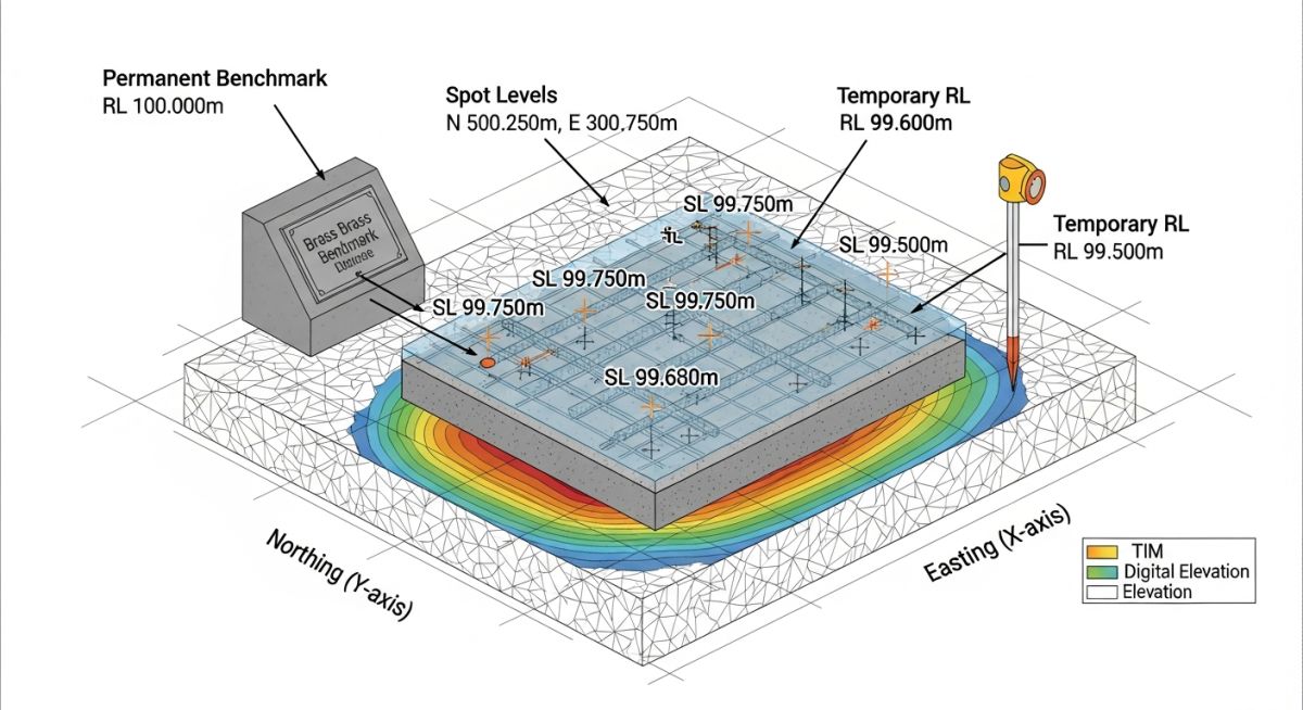
Horizontal control is managed through Northing and Easting coordinates. These values define the position of a point on a 2D plane. In industrial projects, we often use a local grid system that aligns with the plant’s main pipe racks or battery limits. This simplifies the calculation of pipe lengths and equipment spacing. However, you must always maintain a transformation matrix between the local grid and the global geodetic coordinate system (e.g., UTM or state plane) to ensure compatibility with site-wide master plans.
Engineering Warning: Coordinate System Mismatch
Never assume that the “North” on a site survey drawing is True North. Always check the survey notes for the grid orientation. A rotation error of even one degree can lead to significant misalignment of long-run pipe racks over a large site area, resulting in costly field modifications.
Modern surveying relies heavily on Digital Terrain Models (DTM) and Triangulated Irregular Networks (TIN). A DTM is a digital representation of the land surface topography. The TIN is the underlying mathematical structure, created by connecting survey points into a network of non-overlapping triangles. This allows us to calculate cut-and-fill volumes for site grading with high accuracy, ensuring that our underground piping and foundation depths are optimized for the actual terrain.
When reviewing these models, I look for the density of Spot Levels. A spot level is a specific point measurement of elevation. If the density of spot levels is too low in areas with complex terrain, the resulting DTM will be inaccurate, leading to potential clashes between underground utilities and structural foundations. Always ensure your survey scope specifies the required density of spot levels based on the complexity of the site.
Surveying Methodology Assessment: A critical evaluation of the benefits and limitations inherent in modern topographical survey techniques for industrial engineering applications.
Advantages
- High-precision data enables accurate pipe stress analysis.
- DTM models significantly reduce earthwork estimation errors.
- Grid-based coordinates simplify multi-disciplinary design integration.
- Permanent benchmarks ensure long-term construction consistency.
- Automated data collection reduces human transcription errors.
Disadvantages
- High initial cost for professional survey equipment and labor.
- Susceptibility to data corruption if coordinate systems are mixed.
- Requires constant maintenance of physical site benchmarks.
- Dense vegetation can obscure ground levels, requiring manual clearing.
- Software compatibility issues between survey data and CAD/BIM tools.
Topographical Survey Implementation: The practical application of survey data across various phases of industrial facility design, construction, and operational maintenance.
Greenfield Plant Site Grading
Before any foundation work begins, a comprehensive DTM is used to optimize the site’s cut-and-fill balance. This minimizes the need for importing or exporting soil, which is a major cost driver in large-scale industrial projects.
Underground Piping Clash Detection
By overlaying the DTM with the proposed underground piping network, engineers can identify potential conflicts with existing site topography. This allows for the adjustment of pipe inverts before excavation begins, preventing costly field re-routing.
Pipe Rack Elevation Control
Precise RL values are used to set the base elevation of pipe rack steel. This ensures that the gravity-fed lines, such as oily water sewers or process drains, maintain the required slope across the entire length of the rack.
Brownfield Expansion Tie-ins
When adding new units to an existing facility, accurate survey data is used to tie into the existing grid. This ensures that new pipe racks align perfectly with existing structures, preventing misalignment at critical tie-in points.
In my two decades of piping and civil site coordination, I have observed that the primary cause of field rework is the misinterpretation of survey data precision. When we integrate Topographical Surveys into our piping design software, we must ensure that the vertical and horizontal tolerances align with the specific project phase, whether it is conceptual routing or final construction-grade grading plans.
The following table outlines the standard accuracy requirements I enforce for various project stages. These values are derived from ASCE guidelines for site development. Note that as we move from preliminary site selection to final piping rack installation, the required precision for Reduced Levels (RL) and grid coordinates tightens significantly to prevent interference with underground utilities or existing structural foundations.
| Survey Phase | Horizontal Tolerance | Vertical (RL) Tolerance | Primary Application |
|---|---|---|---|
| Conceptual Design | +/- 500 mm | +/- 100 mm | Route Feasibility |
| FEED Phase | +/- 100 mm | +/- 20 mm | Equipment Layout |
| Detailed Engineering | +/- 10 mm | +/- 5 mm | Piping Rack Erection |
Always verify that your survey team is using a calibrated ISO-certified total station. Discrepancies between the site datum and the design model are the most frequent source of costly field modifications during the piping installation phase.
Effective site management requires a clear understanding of how various survey entities interact within a 3D environment. In my experience, engineers often confuse the mathematical representation of a surface with the physical reality of the ground. The matrix below maps these technical entities to their respective roles in our engineering workflows, ensuring that every team member understands the distinction between a raw point cloud and a processed Digital Terrain Model (DTM).
By standardizing our terminology, we reduce the risk of data corruption when importing survey files into CAD or BIM environments. Whether you are dealing with Triangulated Irregular Networks (TIN) or simple spot levels, the following mapping provides the necessary context for high-fidelity site modeling.
| Entity | Acronym | Function | Standard Ref |
|---|---|---|---|
| Reduced Level | RL | Elevation relative to datum | ASME B31.3 |
| Digital Terrain Model | DTM | 3D surface representation | ISO 19157 |
| Triangulated Irregular Network | TIN | Surface mesh geometry | ASTM D6232 |
Use this matrix as a reference during project kick-off meetings to ensure that the survey deliverables match the requirements of your piping stress analysis and civil foundation design teams.
Site Survey Verification: Before finalizing any piping layout, I mandate a rigorous verification of the survey data against the physical site conditions. This process ensures that the digital model accurately reflects the reality of the terrain, preventing clashes with existing underground infrastructure or unexpected elevation changes that could impact gravity-fed piping systems.
-
[ ]
Datum Validation: Confirm that the site datum matches the project master coordinate system and that all benchmarks are clearly marked and undisturbed. -
[ ]
Benchmark Integrity: Verify that at least three permanent benchmarks are established on-site to allow for independent cross-checking of RL values. -
[ ]
Grid Alignment: Ensure that the Northing and Easting coordinates are consistent with the site plot plan and that the rotation angle is correctly applied. -
[ ]
DTM Density: Check that the DTM surface density is sufficient to capture critical slope changes, especially in areas designated for drainage or heavy equipment pads. -
[ ]
Obstruction Mapping: Confirm that all existing above-ground structures and underground utility markers are accurately represented as spot levels.
By following this checklist, you mitigate the risk of “survey drift,” where cumulative errors in measurement lead to significant discrepancies in the final construction phase. Always document the verification results in the project survey log, referencing the specific ASCE standards for site development to maintain audit compliance.
The Problem: Misaligned Datum in a Brownfield Expansion
During a major brownfield expansion, the survey team utilized a local datum that differed from the existing plant coordinate system, leading to a 500mm vertical discrepancy in the piping rack foundation elevations.
- Inconsistent reference to the Mean Sea Level (MSL) datum.
- Failure to verify existing plant benchmarks before starting the survey.
- Lack of communication between the civil survey team and the piping design lead.
- Inadequate cross-referencing of historical site survey data.
The Outcome: Corrective Action and Process Improvement
We successfully rectified the issue by performing a site-wide re-survey using a unified datum and implementing a mandatory benchmark verification protocol for all future site activities.
- Achieved 100% alignment between the new survey data and the existing plant model.
- Reduced foundation rework costs by approximately 40% on subsequent project phases.
- Established a permanent site benchmark network for all future contractors.
- Improved inter-departmental coordination through standardized survey reporting templates.
My recommendation is to always perform a “sanity check” by comparing at least three known points on-site against the survey data before proceeding with any detailed engineering or construction activities.
What is the difference between a Benchmark and a Spot Level?
- Benchmarks serve as the foundation for all vertical control on a project.
- Spot levels are used to populate the DTM and provide granular detail for grading.
- Benchmarks are rarely moved, whereas spot levels are transient data points.
How does a DTM differ from a TIN surface?
- TINs are ideal for complex terrains with irregular features.
- DTMs can also be represented by grid-based models (DEMs).
- TINs provide higher accuracy in areas with dense, non-uniform survey data.
Why are Northing and Easting coordinates critical for piping?
- Coordinates prevent clashes between piping and structural steel.
- They allow for the integration of multiple design models into a single master file.
- Accurate coordinates are essential for automated fabrication and installation processes.
What is the role of a Datum in survey accuracy?
- Always verify the datum against the project’s master survey control plan.
- Ensure that all subcontractors are using the same datum to avoid data misalignment.
- Document the datum source in the project’s technical specifications.
How do I ensure my survey data is compliant with ASME standards?
- Maintain calibration records for all survey instruments.
- Use standardized reporting formats for all survey deliverables.
- Conduct independent verification of critical survey points.
What are the most common causes of survey errors?
- Human error during data entry or instrument setup.
- Equipment drift due to lack of regular calibration.
- Environmental factors like extreme temperatures affecting instrument precision.
- Inadequate site control and benchmark maintenance.
Complete Course on
Piping Engineering
Check Now
Key Features
- 125+ Hours Content
- 500+ Recorded Lectures
- 20+ Years Exp.
- Lifetime Access
Coverage
- Codes & Standards
- Layouts & Design
- Material Eng.
- Stress Analysis