Master Hydraulic Calculation in Piping Networks using Darcy-Weisbach and Hazen-Williams. Learn pressure drop analysis, flow velocity limits, and ASME B31.3 standards.
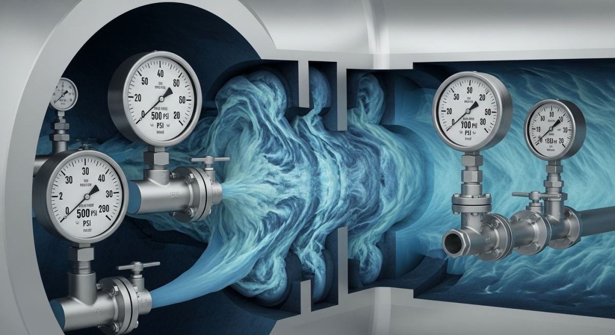
Master Hydraulic Calculation in Piping Networks using Darcy-Weisbach and Hazen-Williams. Learn pressure drop analysis, flow velocity limits, and ASME B31.3 standards.
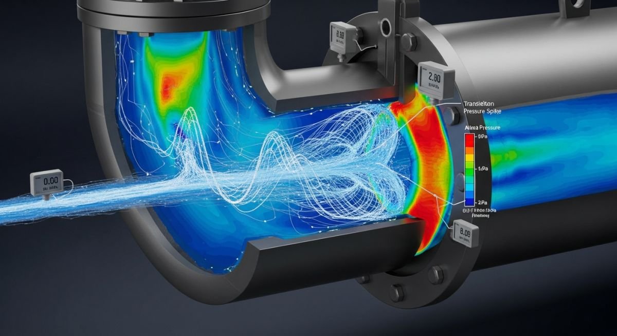
Master Water Hammer Basics in Pumps. Learn to calculate pressure surges, prevent pipe damage, and ensure system reliability using ASME B31.3 standards.
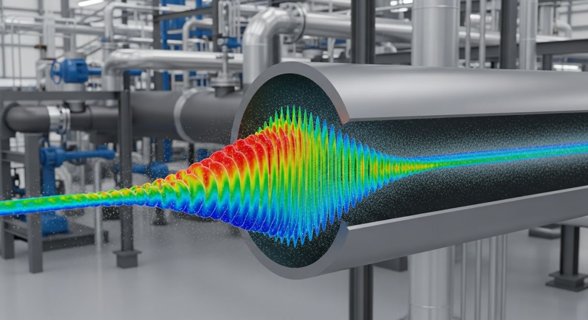
Master Pressure Surge Analysis to prevent catastrophic piping failure. Learn hydraulic transient modeling, wave speed calculations, and mitigation strategies for safe operations.
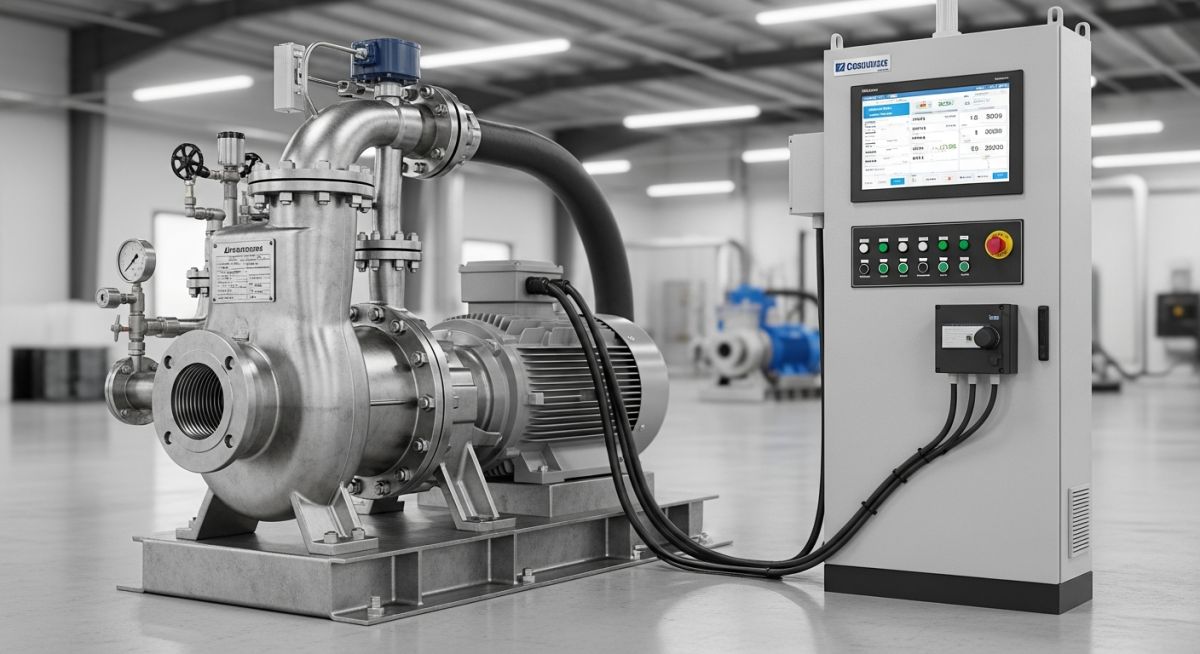
Learn how centrifugal pumps with speed control optimize flow rates, reduce energy consumption, and extend equipment lifespan in industrial systems.
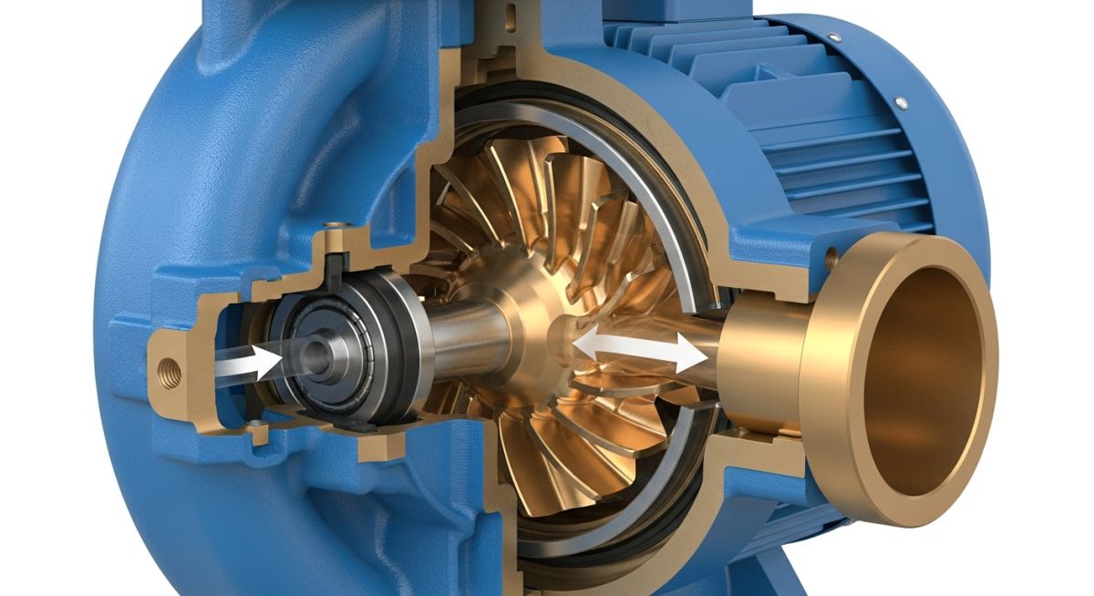
Discover how centrifugal pumps work, explore their main types, and learn how to select the right pump for your industrial applications.
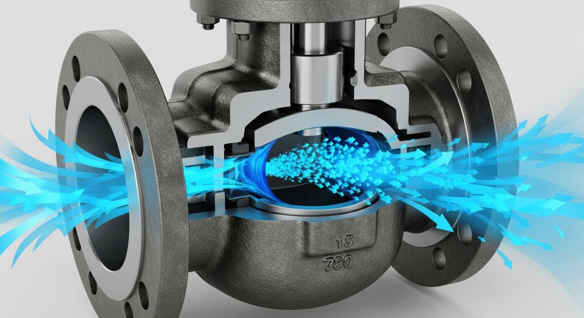
Learn what valve coefficient (Cv) is, how to calculate it, and why choosing the right Cv is critical for efficient piping and flow control systems.
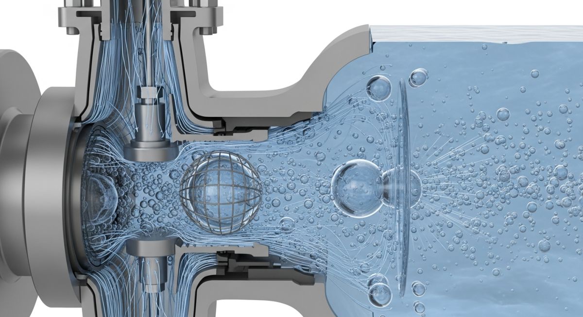
Learn the differences between choked flow, cavitation, and flashing in control valves, their causes, and how to prevent valve damage.
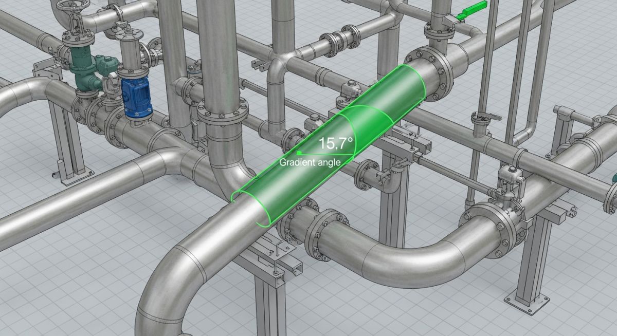
Learn what piping slope is, why it is critical for fluid flow, and how to perform accurate pipe slope calculations for engineering designs.
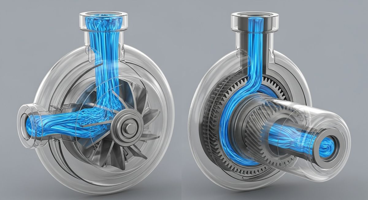
Learn the key differences between centrifugal and positive displacement pumps, including working principles, flow rates, and best applications.
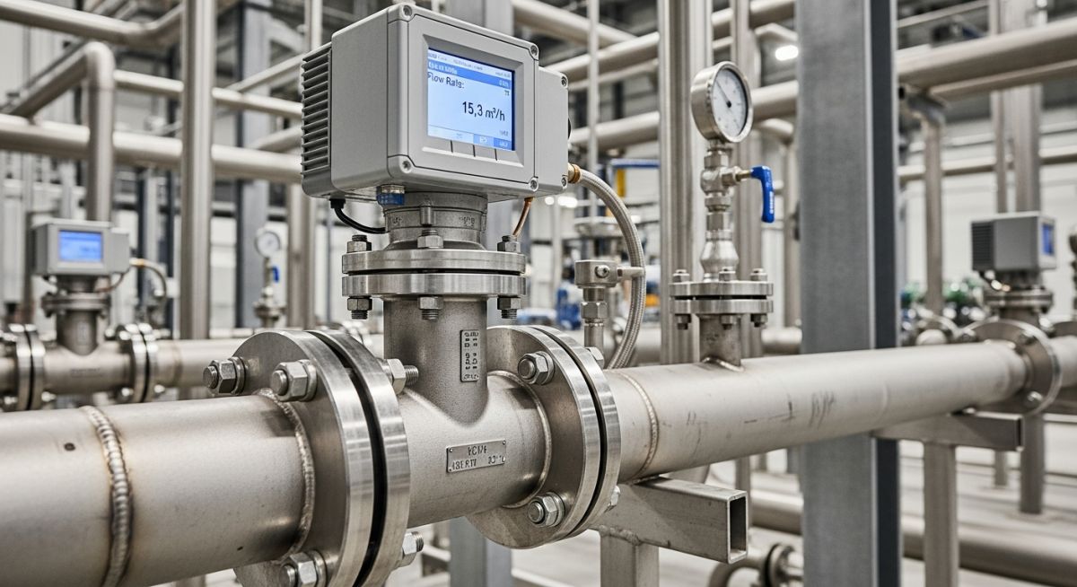
Learn how a vortex flow meter works, its key types, industrial applications, and why it is crucial for accurate fluid measurement.
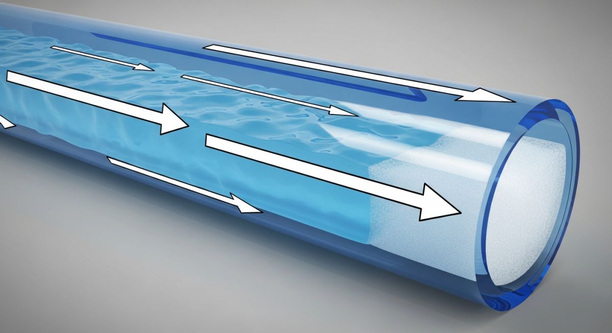
Learn what slug flow is, its hazards in piping systems, and the essential steps for slug flow analysis and prevention in engineering.
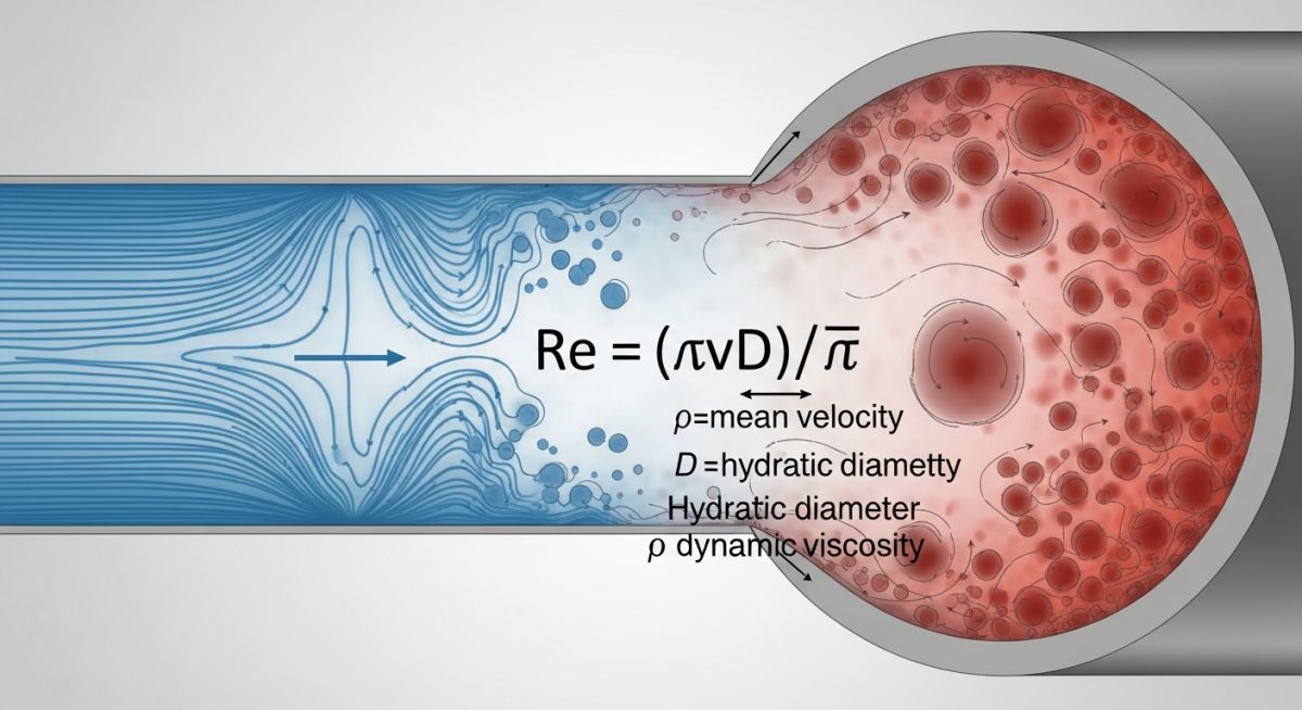
Learn what the Reynolds number is, its formula, and its significance in fluid mechanics. Discover laminar vs. turbulent flow applications.