Understanding Centrifugal Pumps Working and Types for Industrial Plants
In my 20-plus years of designing piping systems and selecting rotating equipment, I have seen too many engineers treat centrifugal pumps as simple black boxes. They drop a pump symbol onto a P&ID, match the nozzle sizes to the pipe, and assume the hydraulic magic will handle itself. This oversight is precisely why mechanical seals fail prematurely, bearings overheat, and cavitation destroys expensive impellers within weeks of commissioning.
To build a reliable process plant, you must master the physical laws governing fluid acceleration and the mechanical nuances of different pump configurations. Whether you are handling volatile hydrocarbons in a refinery or corrosive slurries in a chemical plant, selecting the correct pump geometry is the difference between continuous uptime and costly emergency shutdowns. Let us break down the core mechanics and classifications that define these workhorses of modern industry.
Key Engineering Takeaways
- Understand how kinetic energy is converted to static pressure within the volute casing.
- Identify the critical differences between radial, mixed, and axial flow impellers.
- Learn to evaluate Net Positive Suction Head (NPSH) margins to prevent localized boiling and cavitation.
- Recognize when to specify heavy-duty API 610 pumps versus standard ASME B73.1 chemical process pumps.
How Centrifugal Pumps Working and Types Impact Performance
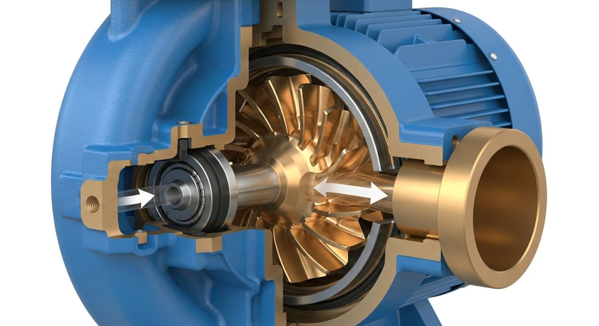
At its core, a centrifugal pump is a dynamic machine. Unlike positive displacement pumps that trap and force a specific volume of fluid, a centrifugal pump relies on dynamic fluid acceleration. The process begins when fluid enters the pump suction nozzle and is directed into the eye of the rotating impeller. As the impeller spins, it imparts kinetic energy to the fluid, slinging it outward toward the outer diameter of the impeller vanes via centrifugal force.
This rapid acceleration increases the fluid’s velocity. However, high velocity alone does not help us push fluid through miles of piping or up into high-pressure distillation columns. We need static pressure. This conversion of kinetic energy (velocity) into potential energy (pressure) occurs within the pump casing.
In a standard volute pump, the casing is designed as a spiral with a progressively expanding cross-sectional area. As the fluid exits the impeller and travels through this expanding spiral toward the discharge nozzle, its velocity naturally decreases. According to Bernoulli’s principle, this deceleration causes a corresponding rise in static pressure.
Operating a centrifugal pump below its Minimum Continuous Stable Flow (MCSF) limits causes severe internal recirculation. This leads to localized pressure drops, thermal expansion of the shaft, rapid mechanical seal degradation, and high-frequency vibration that can shatter carbide seal faces.
The Governing Equations of Pump Hydraulics
To predict how a pump will perform, we rely on Euler’s pump equation. This fundamental relationship defines the theoretical head developed by an impeller based on velocity vectors at the inlet and outlet:
Where:
• H is the total theoretical head (meters)
• u1 and u2 are the peripheral velocities of the impeller at the inlet and outlet (meters per second)
• vu1 and vu2 are the tangential components of the fluid velocity (whirl velocity) at the inlet and outlet (meters per second)
• g is the acceleration due to gravity (9.81 meters per second squared)
In practical applications, we also evaluate the pump’s Specific Speed (Ns), a dimensionless index that describes the geometry of the impeller. Specific Speed is calculated using the following formula:
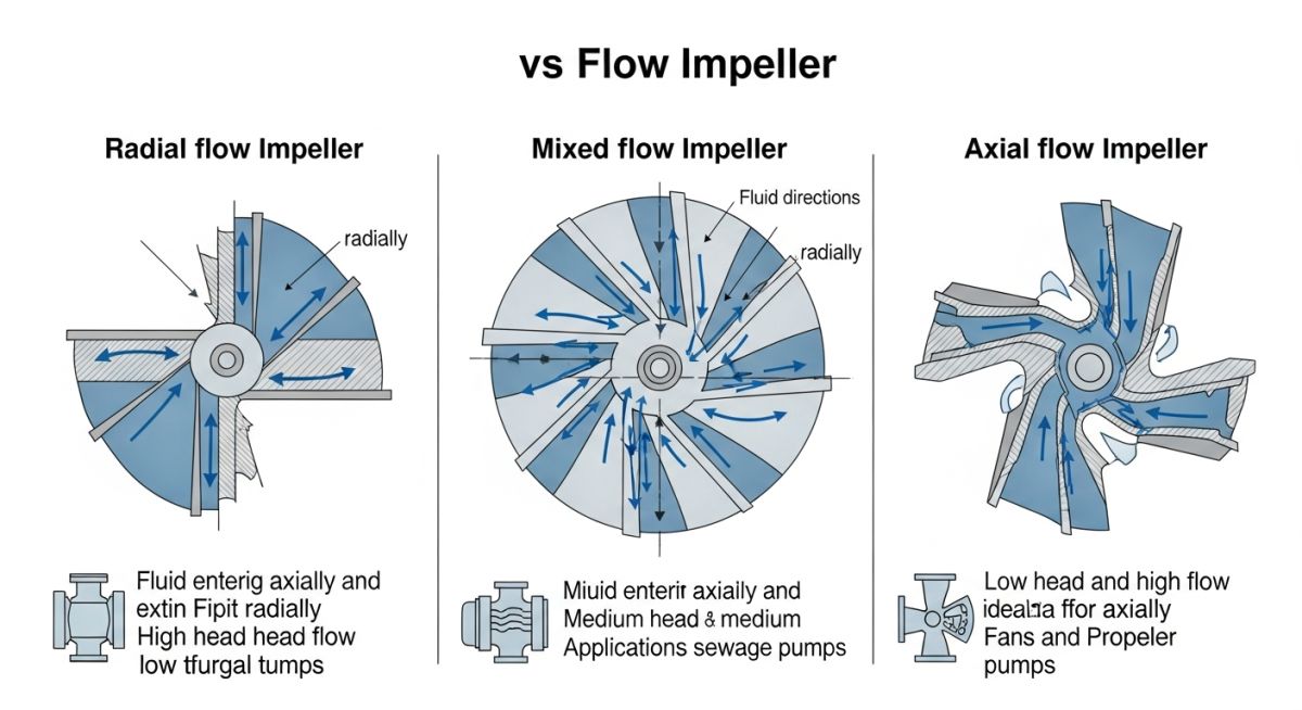
Where N is the rotational speed (RPM), Q is the flow rate at the Best Efficiency Point (BEP) in cubic meters per second, and H is the head per stage at the BEP in meters. Low specific speed impellers are narrow and radial, producing high head at low flow. High specific speed impellers are wide and axial, producing high flow at low head.
Understanding Net Positive Suction Head (NPSH)
Cavitation is the single greatest enemy of centrifugal pumps. It occurs when the local static pressure within the pump—typically at the eye of the impeller—drops below the vapor pressure of the liquid at the operating temperature. When this happens, the liquid boils, forming tiny vapor bubbles. As these bubbles travel into regions of higher pressure further along the impeller vane, they collapse violently. This implosion generates localized shockwaves of up to 100,000 PSI, literally eroding the metal surfaces.
To prevent this, the Net Positive Suction Head Available (NPSHa) at the pump suction nozzle must always exceed the Net Positive Suction Head Required (NPSHr) by the pump manufacturer, typically with a safety margin of at least 1.0 meter or 1.3 times the NPSHr:
Where:
• Ha is the absolute pressure on the surface of the liquid in the suction vessel.
• Hs is the static height of the liquid level above or below the pump centerline (positive for flooded suction, negative for suction lift).
• Hf is the frictional head loss in the suction piping system.
• Hvp is the vapor pressure of the liquid at the operating temperature.
Selecting the Right Impeller for Process Fluids
Selecting the correct impeller geometry is a critical step during the engineering phase of any project. Standardizing on a single impeller type across an entire facility is a recipe for operational failure. Use the table below to match your fluid properties with the correct impeller design.
| Impeller Type | Solids Handling | Hydraulic Efficiency | Typical Applications | Structural Rigidity |
|---|---|---|---|---|
| Open Impeller | Excellent (up to 10% solids) | Low (60% to 70%) | Paper pulp, sewage, food processing slurries | Low (requires frequent clearance adjustments) |
| Semi-Open Impeller | Moderate (up to 5% solids) | Medium (70% to 80%) | Chemical process lines, fibrous liquids | Medium (back shroud provides support) |
| Closed Impeller | Poor (clean liquids only) | High (80% to 90%) | Water distribution, hydrocarbons, clean chemicals | High (double shroud prevents vane deflection) |
Technical Mapping & Specifications Matrix
When specifying pumps for industrial projects, you must align your design parameters with international standards. The matrix below maps key technical entities, physical parameters, and their corresponding design codes.
| Entity / Acronym | Physical Parameter | Standard Reference | Engineering Limit / Rule of Thumb |
|---|---|---|---|
| OH2 (Overhung Single Stage) | Centerline-mounted casing | API 610 | Max temperature 260°C without cooling jackets |
| BB3 (Between Bearings) | Axially split, multistage | API 610 | Used for high-pressure water injection and pipelines |
| ANSI B73.1 Pump | Foot-mounted casing | ASME B73.1 | Limited to 150 PSI rating at ambient temperature |
| VS4 (Vertical Sump) | Line-shaft suspended | API 610 | Sump depth limited to 6 meters to prevent shaft whip |
Pre-Commissioning Checklist for Centrifugal Pumps
Before you press the start button on a newly installed centrifugal pump, you must verify that the mechanical installation matches the design intent. Skipping these steps can result in immediate shaft deflection, seal blowout, or motor burnout.
Step-by-Step Field Verification Protocol
-
Shaft Alignment: Perform cold laser alignment between the pump and motor shafts. Ensure parallel misalignment is under 0.05 mm and angular misalignment is under 0.03 mm.
-
Piping Strain Check: Loosen the pump flange bolts while monitoring a dial indicator on the pump shaft. If the shaft moves more than 0.05 mm, the piping must be modified to eliminate external strain.
-
Mechanical Seal Flush: Verify that the seal flush piping matches the specified API Plan (e.g., Plan 11, 21, or 53A). Ensure all orifice plates are clear and bypass valves are locked open.
-
Casing Venting and Priming: Open the high-point vent valve on the pump casing until a steady stream of liquid exits, ensuring all trapped air is purged from the volute.
-
Motor Rotation Check: Uncouple the motor and bump-start it to verify that the rotation direction matches the arrow cast onto the pump casing.
Analyzing Centrifugal Pumps Working and Types in Action
Field Case Study: Real-World Application
A chemical processing plant in Texas was experiencing chronic mechanical seal failures on a group of single-stage, foot-mounted chemical process pumps handling 30% sodium hydroxide at 65°C. The seals were failing every three to four months, resulting in hazardous chemical leaks and high maintenance costs.
Upon field inspection, I noted that the pumps were vibrating heavily (vibration velocity exceeding 8.2 mm/s RMS) and emitting a distinct crackling sound, resembling pumping gravel. The plant operators had throttled the discharge valves to control the flow rate, forcing the pumps to operate at roughly 35% of their Best Efficiency Point (BEP).
I performed a system head curve analysis and discovered that the pumps were significantly oversized. The high discharge throttling had pushed the operating point deep into the suction recirculation zone, causing classic low-flow cavitation.
To resolve this, we took two actions:
1. We trimmed the impellers from their original 210 mm diameter down to 185 mm to match the actual system head requirements.
2. We installed a minimum flow bypass line back to the suction vessel, controlled by an automatic recirculation valve (ARV).
These modifications shifted the operating point back to 85% of the BEP. Vibration levels dropped immediately to 1.8 mm/s RMS, the crackling noise disappeared, and the mechanical seals have now run for over three years without a single failure.
This case highlights a common industry mistake: sizing a pump with too much “safety margin” and then throttling the discharge to compensate. Always design your piping systems and select your pump types based on realistic operating scenarios, not worst-case compounding safety factors.
Frequently Asked Engineering Questions
What is the difference between API 610 and ASME B73.1 pumps?
How do you prevent cavitation in centrifugal pumps?
What is the significance of the Best Efficiency Point (BEP)?
Why must a centrifugal pump be primed before startup?
What is the difference between radial flow and axial flow impellers?
How does viscosity affect centrifugal pump performance?
===FAQ_BLOCK===
Complete Course on
Piping Engineering
Check Now
Key Features
- 125+ Hours Content
- 500+ Recorded Lectures
- 20+ Years Exp.
- Lifetime Access
Coverage
- Codes & Standards
- Layouts & Design
- Material Eng.
- Stress Analysis



