Introduction to Pressure Surge Analysis for Piping Systems
In my two decades of field experience, I have seen too many catastrophic failures caused by the simple, yet often overlooked, phenomenon of water hammer. When a valve closes rapidly or a pump trips unexpectedly, the kinetic energy of the moving fluid must go somewhere. This energy converts into a pressure wave that travels at the speed of sound through your piping, often exceeding the design pressure of the system by several hundred percent.
Mastering pressure surge analysis is not just about theoretical fluid dynamics; it is about protecting your assets and personnel from the violent forces of hydraulic shock. This guide breaks down the complex wave speed calculations and modeling techniques required to maintain structural integrity in high-pressure process environments.
Key Takeaways
- Understand the Joukowsky equation for calculating maximum pressure rise.
- Identify critical transient events: pump trips, rapid valve closure, and check valve slam.
- Learn how to select appropriate mitigation devices like surge tanks and relief valves.
- Ensure compliance with API 521 for pressure-relieving systems.
Technical Fundamentals of Pressure Surge Analysis
Pressure Surge Analysis: A rigorous engineering methodology used to quantify the magnitude and duration of pressure spikes resulting from rapid changes in fluid velocity, ensuring piping systems adhere to ASME B31.3 pressure-temperature ratings.
When fluid velocity changes abruptly, the resulting pressure wave propagates through the pipe at the speed of sound in the fluid, modified by the elasticity of the pipe wall. The fundamental calculation for the maximum pressure rise is the Joukowsky equation: delta P equals rho times a times delta v. Here, rho is the fluid density, a is the wave speed, and delta v is the change in velocity.
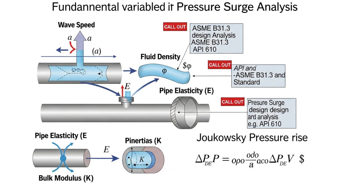
Calculating the wave speed (a) is critical. It depends on the bulk modulus of the fluid, the Young’s modulus of the pipe material, the pipe diameter, and the wall thickness. For thin-walled pipes, we must account for the hoop stress and the Poisson effect. If the valve closure time is less than the round-trip time of the wave (2L/a), the system experiences a full surge pressure.
Field Warning: The “Rapid Closure” Trap
Many designers assume that slow-closing valves are safe. However, if the closure time is not significantly greater than the wave reflection time, the system will still experience a significant pressure spike. Always perform a transient simulation for any valve closure under 30 seconds in large-bore liquid lines.
In my experience, the most common oversight is neglecting the interaction between the fluid and the pipe structure. The pipe is not a rigid container; it expands and contracts during a surge. This structural response can actually lower the wave speed, but it also introduces cyclic stresses that can lead to fatigue failure over time. We must evaluate these transients against the allowable stress range defined in ASME B31.3, specifically checking the occasional load limits.
To model these events, we utilize the Method of Characteristics (MOC). This numerical technique solves the partial differential equations of continuity and momentum by transforming them into ordinary differential equations along characteristic lines. Modern software packages automate this, but you must verify the input parameters—specifically the valve closure characteristics and pump inertia—to ensure the model reflects reality.
Transient Modeling Benefits: The application of advanced hydraulic simulation to predict system behavior under non-steady state conditions, preventing catastrophic failure and optimizing capital expenditure on surge protection equipment.
Advantages
- Prevents catastrophic pipe rupture by identifying peak pressure zones.
- Optimizes wall thickness requirements, potentially reducing material costs.
- Extends equipment life by minimizing cyclic fatigue on pump seals and valve seats.
- Ensures regulatory compliance with safety standards like API 521.
- Allows for the precise sizing of surge relief valves and accumulators.
Disadvantages
- Requires high-fidelity data on valve closure curves and pump inertia.
- Software modeling can be time-intensive for complex, branched piping networks.
- Risk of “garbage in, garbage out” if fluid properties are incorrectly defined.
- Mitigation hardware (surge tanks) adds significant footprint and maintenance requirements.
- Over-conservative modeling can lead to unnecessary, expensive pipe wall thickness increases.
Industrial Surge Mitigation: The deployment of transient analysis across diverse sectors to manage fluid energy and maintain system integrity during emergency shutdowns and operational transitions.
Long-Distance Water Transmission
In municipal water supply lines spanning dozens of kilometers, pump trips create massive pressure waves that can burst pipes miles away from the source. Transient analysis allows engineers to place surge anticipator valves at strategic high-elevation points to dissipate energy before it reaches critical infrastructure.
Refinery Feedstock Pumping
Refineries often handle volatile hydrocarbons where a pressure surge could lead to a loss of containment and fire. By modeling the rapid closure of emergency shutdown valves, we can determine if the existing piping schedule is sufficient to handle the transient peak or if additional dampening is required.
Cryogenic LNG Loading Systems
LNG loading arms are extremely sensitive to pressure surges due to the rapid change in fluid density and temperature. Transient analysis is mandatory here to prevent check valve slam, which can cause severe mechanical damage to the loading arm swivel joints and cryogenic seals.
In my two decades of piping design, I have found that accurate hydraulic transient modeling relies heavily on the precision of input parameters. When performing a pressure surge analysis, engineers must account for the fluid bulk modulus, pipe wall elasticity, and the specific geometry of the piping system. These variables dictate the celerity of the pressure wave, which is the fundamental speed at which a disturbance travels through the fluid column.
The following table summarizes the critical physical properties and design coefficients required for standard ASME B31.3 compliant systems. Using incorrect values for the modulus of elasticity or fluid density can lead to significant errors in peak pressure estimation, potentially resulting in the under-design of surge protection devices like relief valves or surge tanks. Always verify these values against the specific fluid data sheets and material test reports for your project.
| Parameter | Symbol | Typical Unit | Application |
|---|---|---|---|
| Fluid Bulk Modulus | K | Pa (N/m2) | Wave Speed Calculation |
| Pipe Modulus of Elasticity | E | GPa | Wall Deformation Analysis |
| Fluid Density | rho | kg/m3 | Inertial Force Modeling |
| Pipe Wall Thickness | t | mm | Hoop Stress Calculation |
By maintaining this data matrix, you ensure that your simulation software—whether it be AFT Impulse or similar transient solvers—receives the high-fidelity data necessary for accurate results. Remember that temperature fluctuations can significantly alter the bulk modulus of liquids, so always perform sensitivity analyses if your process operates across a wide thermal range.
Effective pressure surge analysis requires a structured approach to mapping physical entities to their corresponding mathematical representations. In my experience, the most common failure in transient modeling is the disconnect between the physical piping layout and the simplified node-branch network used in software. This matrix serves as a bridge, linking critical engineering components to their governing standards and analytical roles.
When you define your system, you must categorize each component based on its impact on the pressure wave. For instance, a check valve is not just a flow control device; it is a potential source of rapid flow reversal, which can trigger severe water hammer events. By mapping these components to their respective API and ASME standards, you ensure that your mitigation strategies are not only effective but also code-compliant.
| Entity | Standard | Transient Role |
|---|---|---|
| Check Valve | API 594 | Flow Reversal Trigger |
| Pressure Relief Valve | API 520/521 | Surge Mitigation |
| Piping System | ASME B31.3 | Wave Propagation Path |
| Surge Tank | ASME BPVC VIII | Energy Dissipation |
This mapping matrix should be updated throughout the project lifecycle as the piping design matures. If you change a valve type or adjust the pipe wall schedule, ensure that the transient model is updated to reflect these changes, as they directly influence the wave speed and the resulting peak pressure loads on your supports and anchors.
Before finalizing any hydraulic transient model, I always conduct a rigorous site verification process. Theoretical models often fail to account for real-world installation nuances, such as air pockets, partially closed valves, or non-standard pipe supports. This checklist ensures that your analytical assumptions align with the physical reality of the piping system.
-
[ ]
Verify all valve closure times against manufacturer data sheets to ensure realistic transient input. -
[ ]
Confirm the presence and functionality of air release valves at high points to prevent air-induced surge amplification. -
[ ]
Inspect pipe support locations for proximity to high-velocity zones where vibration could lead to fatigue. -
[ ]
Validate the fluid properties, specifically density and viscosity, against actual process operating conditions. -
[ ]
Check for any “dead legs” or stagnant sections that could trap gas and alter the effective wave speed.
When performing these checks, document every deviation from the original design intent. If you find that a valve is closing faster than the design specification, you must re-run the transient simulation to determine if the resulting pressure spike exceeds the allowable stress limits defined in ASME B31.3. Safety is not a one-time calculation; it is a continuous process of verification and adjustment throughout the life of the facility.
Problem: Unexpected Pipe Rupture in High-Pressure Pumping Station
- Rapid closure of a main isolation valve caused a massive pressure surge.
- The existing surge relief system failed to actuate within the required millisecond window.
- Pipe supports were not designed for the dynamic loads generated by the transient event.
- The effective wave speed was higher than estimated due to incorrect pipe wall thickness assumptions.
Outcome: Successful Mitigation and System Stabilization
- Implemented a slow-closing valve actuator to increase closure time from 2 seconds to 15 seconds.
- Installed a bladder-type surge tank to absorb the kinetic energy of the fluid column.
- Updated the piping support design to include dynamic snubbers for better load distribution.
- Achieved a 40 percent reduction in peak transient pressure, bringing the system within safe operating limits.
My recommendation for similar systems is to always prioritize the “prevention over protection” philosophy. While surge tanks and relief valves are necessary, the most effective way to manage pressure surge analysis is to control the source of the transient—the valve closure rate—whenever the process allows.
How does pipe elasticity affect wave speed?
- Rigid pipes result in higher wave speeds and sharper pressure spikes.
- Flexible materials like HDPE significantly dampen the surge by absorbing energy.
- The calculation must include the pipe’s modulus of elasticity and the constraint condition, such as whether the pipe is anchored at one end or throughout its length.
What is the role of the Joukowsky equation?
- It provides a conservative upper bound for surge pressure in simple systems.
- It assumes an instantaneous valve closure, which is rarely achieved in practice.
- Engineers use this as a preliminary screening tool before moving to complex computer-based transient modeling.
When should I use a surge tank?
- They are essential in long-distance pipelines where the reflection time of the pressure wave is significant.
- They help maintain system pressure during pump trips, preventing column separation.
- Design must comply with ASME BPVC Section VIII for pressure vessels.
How does fluid viscosity impact surge?
- In short piping runs, viscosity effects are often negligible compared to inertial effects.
- In long, complex networks, viscosity helps attenuate the peak pressure over time.
- Always ensure your model uses the viscosity at the minimum operating temperature, as this is when the fluid is most resistant to flow.
What is column separation?
- It is common in high-elevation points or after a sudden pump trip.
- Prevention involves maintaining positive pressure using surge tanks or vacuum breakers.
- Modeling this requires advanced software capable of tracking vapor cavity formation and collapse.
Are there specific ASME standards for surge?
- The code requires that the sum of sustained and occasional loads, including pressure surges, does not exceed the allowable stress limits.
- Engineers must use sound engineering judgment and industry-recognized methods to quantify these transient loads.
- Always document your surge analysis methodology in the design basis report to satisfy regulatory and safety audits.
📚 Recommended Resources: Pressure Surge Analysis
Read these Guides
🎥 Watch Tutorials

Complete Course on
Piping Engineering
Check Now
Key Features
- 125+ Hours Content
- 500+ Recorded Lectures
- 20+ Years Exp.
- Lifetime Access
Coverage
- Codes & Standards
- Layouts & Design
- Material Eng.
- Stress Analysis
