Table of Contents
How to Perform Piping Slope Calculation for Industrial Systems
In my 20-plus years of designing process plants, I have seen many systems fail not because of complex stress issues, but because of basic gravity. I remember a project where a massive steam line kept hammering during startup. The culprit? A junior designer assumed water would always find its way out, neglecting the necessary slope.
Piping slope is the unsung hero of process safety. Whether you are dealing with steam condensate, flare headers, or gravity-fed chemical sewers, getting the slope right is the difference between a smooth-running plant and a catastrophic water hammer event. Let us dive deep into how we calculate, verify, and implement these slopes in the real world.
Key Takeaways
- Understand why gravity drainage prevents hazardous condensate pockets in steam lines.
- Master the fundamental mathematical formulas used for daily slope calculations.
- Learn the minimum slope requirements for flare headers, sewers, and process lines.
- Discover field-tested methods to verify piping slope during construction.
- Avoid common design pitfalls that lead to reverse slope and pocketing.
Why is Piping Slope Calculation Critical?
When we design piping systems, we rely on pumps to move fluids. However, for many utility and process lines, pumps are either impractical or economically unfeasible. This is where gravity flow takes over. To make gravity work for us, we must introduce a continuous slope.
Without a proper slope, liquids pool in low spots. In steam systems, this pooled water is picked up by high-velocity steam, creating a slug of liquid that travels at near-sonic speeds. When this slug hits an elbow or valve, the resulting impact—known as water hammer—can easily rupture the pipe. In flare headers, liquid pockets restrict the flow area, causing high backpressure that can compromise the entire relief system.
Never allow a “sag” or reverse slope in any gravity line. Even a minor deviation can trap corrosive fluids, leading to localized pitting corrosion and premature piping failure. Always verify support spacing to prevent mid-span sagging.
The Mathematics of Pipe Slope
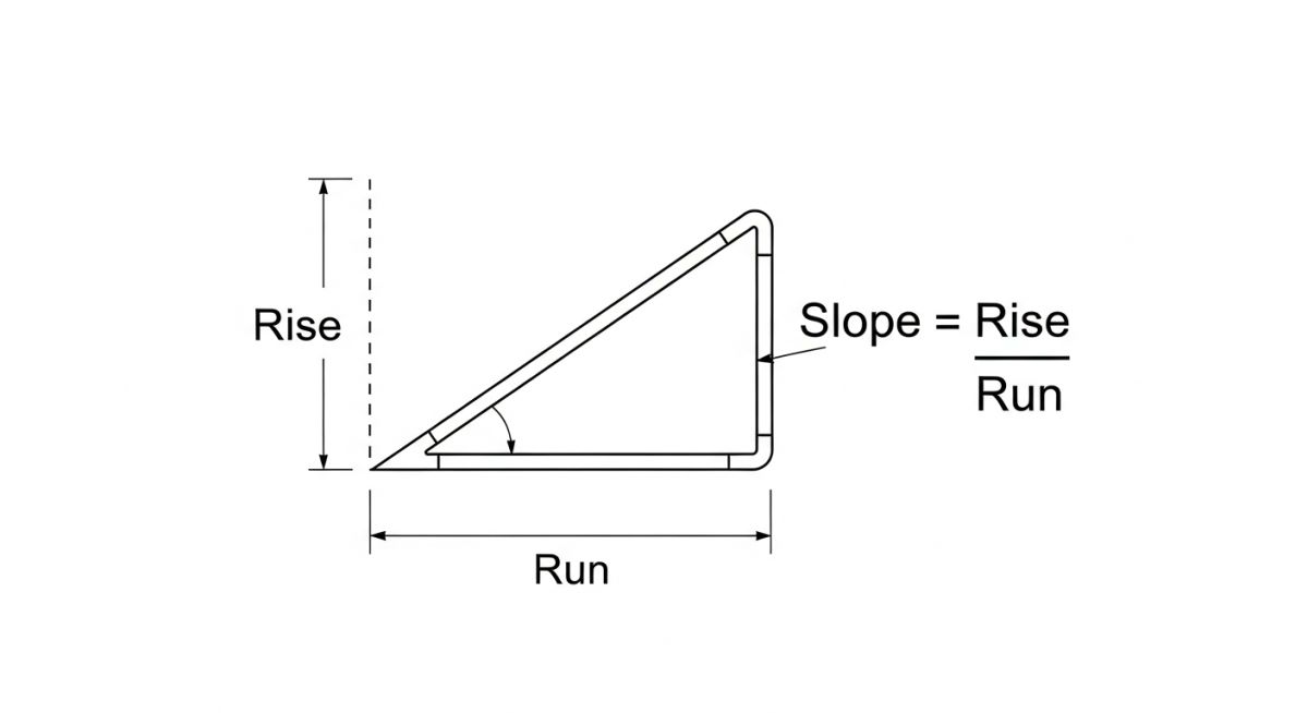
Calculating the slope is straightforward, but it requires absolute precision. The slope is defined as the ratio of the vertical drop to the horizontal run.
Formula 1: Slope Ratio (S)
S = H / L
Where H is the vertical drop (elevation difference) and L is the horizontal run length. Both values must be in the same units (e.g., millimeters or inches).
Formula 2: Percent Slope (P)
P = (H / L) * 100
Formula 3: Slope in Inches per Foot (for US Customary Units)
Slope (in/ft) = (H_inches / L_feet)
Let us look at a practical example. If you have a flare header with a horizontal run of 120 meters, and the process requirements dictate a minimum slope of 0.2 percent, what is the required vertical drop?
H = (P * L) / 100
H = (0.2 * 120) / 100
H = 0.24 meters (or 240 millimeters)
This means the starting point of your flare line must be exactly 240 millimeters higher than the termination point at the knockout drum.
When designing these systems, we must also consult industry standards. ASME B31.3 provides guidance on the structural integrity of process piping, while ASME B31.1 covers power piping, including critical steam condensate lines.
Standard Slope Values for Industrial Piping
Different process services require different slopes. A highly viscous fluid or a line carrying suspended solids requires a steeper slope than a clean, low-viscosity hydrocarbon. Below is a reference table compiled from standard engineering practices and API RP 521 guidelines.
| Service Type | Recommended Minimum Slope (Ratio) | Recommended Minimum Slope (Percentage) | Primary Code Reference |
|---|---|---|---|
| Steam Condensate Lines | 1 in 240 to 1 in 480 | 0.21% to 0.42% | ASME B31.1 |
| Flare Headers (Wet Gas) | 1 in 500 | 0.20% | API RP 521 |
| Gravity Sewers (Chemical/Process) | 1 in 100 to 1 in 200 | 0.50% to 1.00% | ASME B31.3 / Local Codes |
| Oily Water Sewers | 1 in 135 | 0.74% | API RP 500 Series |
| Instrument Air Header Drains | 1 in 100 | 1.00% | ISA-7.0.01 |
Technical Mapping & Specifications Matrix
To ensure your piping slope calculation integrates seamlessly with hydraulic models, you must map the physical parameters correctly. The table below outlines the key variables used in gravity flow calculations.
| Parameter | Acronym/Symbol | Physical Meaning | Reference Standard |
|---|---|---|---|
| Hydraulic Radius | Rh | Ratio of flow area to wetted perimeter | Manning’s Equation |
| Roughness Coefficient | n | Frictional resistance of the pipe wall material | ASME B31.3 Appendix F |
| Froude Number | Fr | Ratio of inertial forces to gravitational forces | Fluid Dynamics Standards |
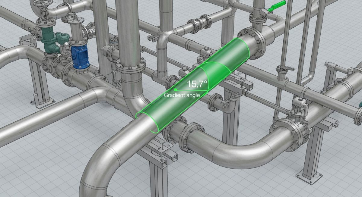
| Slope Angle | theta | Angle of inclination relative to the horizontal plane | ASME B31.1 / B31.3 |
How to Verify Piping Slope Onsite
Even the most perfect 3D CAD model is useless if the field installation is incorrect. During construction, pipe fitters often struggle to maintain exact slopes over long runs. As a quality control engineer or inspector, you must verify these slopes before the system is signed off for hydrotesting.
Field Inspection Checklist
-
Verify Isometric Match: Cross-reference the physical pipe layout with the latest revision of the isometric drawing to confirm the designated high and low points.
-
Check Support Elevations: Measure the elevation of each pipe shoe or hanger. Do not rely solely on the pipe wall, as local deformations can skew measurements.
-
Inspect for Sagging: Ensure the span between supports does not exceed the maximum allowable span specified in ASME B31.3 to prevent mid-span sagging.
-
Calibrate Instruments: Ensure all digital inclinometers or laser levels used for verification have valid calibration certificates.
-
Document As-Built Slopes: Record the actual measured slope at three distinct points along each major run and log them in the quality assurance system.
Field Case Study: Real-World Application
During a routine turnaround at a major petrochemical facility, operators noticed an unexpected pressure drop across the main 24-inch flare header. Upon inspection, we discovered that a 15-meter section of the header had sagged due to a failed spring hanger support. This sag created a massive liquid pocket that trapped heavy hydrocarbons, reducing the effective flow area by nearly 40 percent and risking a catastrophic liquid carryover to the flare tip during a relief event.
My team was called in to perform an emergency piping slope calculation. We recalculated the required drop over the affected 15-meter run to achieve a continuous 1 in 500 slope. We replaced the failed spring hangers with rigid, adjustable pipe shoes, allowing us to fine-tune the elevation. After adjusting the supports, we verified a continuous 0.2% slope using a calibrated digital transit level. The liquid pocket was completely eliminated, and subsequent relief simulations confirmed that backpressure remained well within safe limits.
This case highlights why continuous monitoring and proper support design are just as critical as the initial design calculations. A single failed support can completely negate a well-calculated slope.
Piping Slope Calculation: Frequently Asked Questions
What is the minimum slope for a steam condensate line?
How does pipe diameter affect the required slope?
What happens if a pipe is sloped too steeply?
How do you handle slope transitions at pipe supports?
What is the difference between slope and pitch in piping?
Which standards govern piping slope requirements?
===
Complete Course on
Piping Engineering
Check Now
Key Features
- 125+ Hours Content
- 500+ Recorded Lectures
- 20+ Years Exp.
- Lifetime Access
Coverage
- Codes & Standards
- Layouts & Design
- Material Eng.
- Stress Analysis

📚 Recommended Resources: piping slope calculation
Read these Guides
🎥 Watch Tutorials

Related posts:
![Infographic flowchart of the GRP GRE FRP piping stress analysis workflow in START-PROF.]()
Rigid Struts: Definition, Applications, and Modeling in Caesar II
![3D stress analysis model of GRP piping system in START-PROF software showing stress distribution.]()
Stress Analysis of GRP / GRE / FRP Piping using START-PROF
![Industrial centrifugal pump installed on a concrete foundation with precision piping and alignment.]()
How to Use a Pump Installation Checklist for Maximum Reliability
![3D Caesar II pipe stress analysis model of a centrifugal pump piping system showing stress distribution.]()
Pump-Piping Alignment Caesar II Stress Analysis Methodology
![3D render of a structural steel cross-bracing connection with a gusset plate.]()
Mastering Steel Connections with a Cross-Bracing Design Example
![Industrial engineer checking shaft alignment on a centrifugal pump during commissioning.]()
How to Use a Pump Commissioning Checklist for Start-Up