Table of Contents
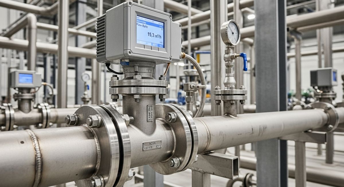
What is a Vortex Flow Meter and How Does It Work
I have spent over two decades in the field, commissioning piping systems and troubleshooting instrumentation in high-pressure steam plants. If there is one instrument that has consistently saved my projects from energy-loss disasters, it is the vortex flow meter. When you are dealing with superheated steam at 300 degrees Celsius, mechanical meters with moving parts will fail within months. That is where the beauty of fluid dynamics comes in. By placing a simple, unmoving obstruction in the flow path, we can force the fluid to tell us exactly how fast it is moving.
- No moving parts means minimal mechanical wear and low maintenance costs.
- Highly accurate for steam, gas, and low-viscosity liquids.
- Requires a minimum Reynolds number of 10,000 to 20,000 for linear, accurate measurement.
- Upstream and downstream straight pipe runs are non-negotiable for hydrodynamic stability.
Complete Course on
Piping Engineering
Check Now
Key Features
- 125+ Hours Content
- 500+ Recorded Lectures
- 20+ Years Exp.
- Lifetime Access
Coverage
- Codes & Standards
- Layouts & Design
- Material Eng.
- Stress Analysis
How Does a Vortex Flow Meter Work
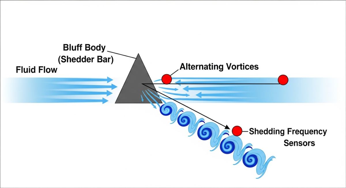
The fundamental physics of a vortex flow meter relies on the Von Karman Vortex Street. When a fluid encounters an obstruction (known as a bluff body or shedder bar), it cannot follow the sharp contours. This causes the flow to separate, creating shear layers that roll up into alternating vortices downstream of the obstruction.
The frequency of these vortices is directly proportional to the velocity of the fluid and inversely proportional to the width of the bluff body. We express this relationship mathematically using the dimensionless Strouhal Number:
Where:
St = Strouhal Number (dimensionless, typically constant around 0.17 to 0.21 for a wide range of Reynolds numbers)
f = Vortex shedding frequency in Hertz (Hz)
d = Width of the bluff body in meters (m)
V = Local fluid velocity in meters per second (m/s)
Real-World Engineering Calculation
Let us calculate the fluid velocity and volumetric flow rate for a DN100 (4-inch) Schedule 40 steam pipe. The internal diameter is 102.3 mm (0.1023 m). We install a vortex flow meter with a bluff body width of 20 mm (0.02 m). The Strouhal number for this specific bluff body geometry is calibrated at 0.17.
If the sensor detects a shedding frequency of 255 Hz, we calculate the fluid velocity as follows:
V = (255 * 0.02) / 0.17
V = 5.1 / 0.17 = 30 meters per second
To find the volumetric flow rate (Q):
Where A is the cross-sectional area of the pipe:
A = pi * (D^2) / 4 = 3.14159 * (0.1023^2) / 4 = 0.00822 square meters
Q = 30 * 0.00822 = 0.2466 cubic meters per second (or 887.8 cubic meters per hour)
In my experience, sensor selection is another critical factor. Most modern vortex meters use piezoelectric sensors embedded behind or within the bluff body to detect the tiny pressure fluctuations caused by the vortices. These sensors must withstand thermal cycling and piping vibration. For high-vibration lines, I always specify dual-sensor designs that cancel out common-mode mechanical noise while isolating the true vortex frequency.
For detailed standards on vortex flow measurement, refer to the ASME MFC-6M and ISA-RP16.5 guidelines.
Sizing Parameters for a Vortex Flow Meter
Selecting the correct meter size is critical. In many cases, the optimum vortex meter size is one size smaller than the nominal pipe size to increase fluid velocity and ensure stable vortex shedding. The table below outlines typical sizing and performance parameters across different process fluids.
| Fluid Type | Velocity Range (m/s) | Min Reynolds Number | Typical K-Factor (pulses/L) | Pressure Drop (kPa) |
|---|---|---|---|---|
| Saturated Steam | 15 to 80 | 20,000 | 1.2 to 5.5 | 10 to 35 |
| Superheated Steam | 20 to 100 | 20,000 | 1.2 to 5.5 | 15 to 50 |
| Clean Water | 0.5 to 7 | 10,000 | 10.5 to 45.0 | 5 to 25 |
| Light Hydrocarbons | 0.8 to 8 | 15,000 | 8.0 to 35.0 | 8 to 30 |
| Compressed Air | 10 to 60 | 15,000 | 2.5 to 12.0 | 12 to 40 |
This matrix maps the core physical parameters, governing equations, and standard references used by piping and instrumentation engineers to design and validate vortex flow meter installations.
| Entity / Acronym | Physical Parameter | Standard Reference | Engineering Significance |
|---|---|---|---|
| St | Strouhal Number | ASME MFC-6M | Determines the linearity of the shedding frequency relative to fluid velocity. |
| Re | Reynolds Number | ISO 5167 | Defines the lower limit of turbulent flow required for stable vortex generation. |
| K-Factor | Calibration Factor | AGA Report No. 11 | Represents the number of pulses generated per unit volume of fluid. |
| DP | Pressure Drop | Crane Technical Paper 410 | Calculates permanent pressure loss across the bluff body to prevent cavitation. |
Field Installation Checklist for Vortex Meters
In my 20 years of field engineering, more than 80% of vortex meter failures I have investigated were caused by poor installation practices rather than instrument defects. Use this checklist on-site before commissioning any vortex flow meter.
-
Upstream Straight Run: Verify a minimum of 10D (10 nominal diameters) of straight, unobstructed pipe upstream of the meter. Increase to 20D or 30D if downstream of control valves or multiple elbows.
-
Downstream Straight Run: Ensure at least 5D of straight pipe downstream to prevent backpressure fluctuations from disrupting the vortex pattern.
-
Gasket Alignment: Confirm that gaskets do not protrude into the flow stream. Even a 1 mm protrusion can generate parasitic vortices that corrupt the primary shedding frequency.
-
Pipe Alignment: The meter must be perfectly concentric with the adjacent piping. Misalignment creates asymmetric velocity profiles.
-
Sensor Orientation: For liquid applications, mount the sensor at the bottom or side to keep it flooded. For steam, mount it horizontally or vertically upward to prevent condensate accumulation on the sensor elements.
-
Grounding: Ensure the meter body is properly grounded to the piping to eliminate electrical noise from nearby motors or variable frequency drives.
Field Case Study: Real-World Application
At a district heating plant in Chicago, a DN150 (6-inch) vortex flow meter measuring superheated steam (180 PSI, 280°C) was reporting highly erratic flow rates. The readings fluctuated by up to 22% compared to the boiler feed water balance. The plant operators suspected a faulty sensor. Upon inspection, I noticed the meter was installed directly downstream of a pressure-reducing valve with only 8D of straight run, and the piping was vibrating heavily due to structural resonance.
Instead of replacing the meter, we modified the piping layout to provide 25D of upstream straight run and installed heavy-duty pipe supports on both sides of the meter. We also adjusted the low-flow cut-off and noise-filtering parameters on the transmitter. These changes eliminated the mechanical noise interference, restoring the meter’s accuracy to within +/- 0.75% of the actual flow rate, saving the plant thousands of dollars in unbilled steam energy.
My recommendation for any high-temperature steam application is to always perform a piping stress and vibration analysis before selecting your meter location. If vibration is unavoidable, use structural pipe clamps to isolate the meter body.
Frequently Asked Engineering Questions
Can a vortex flow meter measure low-velocity fluids?
How does fluid viscosity affect vortex shedding?
What is a multivariable vortex flow meter?
Why is cavitation a problem for vortex meters in liquid service?
How do you calibrate a vortex flow meter?
Can vortex meters handle wet steam?
===

📚 Recommended Resources: Vortex Flow Meter
Related posts:
![Comparison of raw PTFE material and an industrial PTFE-lined steel pipe flange]()
Teflon vs PTFE: Major Differences in Industrial Piping Applications
![Severe metal galling damage on a stainless steel threaded bolt and nut.]()
What is Metal Galling and How to Prevent It
![Certified welder performing structural welding repair on a heavy steel beam with sparks flying.]()
Mastering Industrial Welding Repair Procedures for Structural Integrity
![A fully assembled industrial pump skid system with stainless steel piping and control panels in a factory.]()
What is an Industrial Pump Skid and Its Key Advantages?
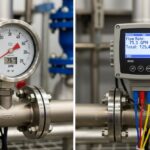
![Side-by-side comparison of an industrial flow meter and a digital flow transmitter installed on a pipeline.]()
Flow Transmitter vs Flow Meter: Key Differences Explained
![Wireless vibration sensor mounted on an industrial electric motor for condition monitoring.]()
What is Vibration Monitoring and Why is it Important?