How to Master Supporting Dual Insulated Piping Systems Safely
In my 20 plus years of experience designing piping systems for cryogenic and high-temperature petrochemical plants, few challenges compare to the complexity of supporting dual insulated piping. When you are dealing with a system that has both an inner carrier pipe and an outer containment jacket—each operating at vastly different temperatures—standard pipe clamps simply will not cut it. If you clamp the outer jacket directly to structural steel without a thermal barrier, you create a massive thermal bridge. This bridge leads to localized condensation, ice formation, or extreme heat loss, which rapidly destroys the insulation and causes structural failure of the jacket.
I have seen multi-million dollar LNG facilities suffer from severe piping deformation because the design team treated dual-insulated lines like standard insulated utility lines. Designing these supports requires a deep understanding of compressive strength, vapor barrier continuity, and differential thermal movement. In this guide, I will share the exact engineering principles, calculations, and field-proven practices I use to ensure these systems operate safely and efficiently over their entire design life.
Key Engineering Takeaways
- Understand how to calculate localized compressive stress on high-density polyurethane foam (HDPEF) and cellular glass inserts.
- Learn to maintain 100% vapor barrier integrity at support locations to prevent moisture ingress and corrosion under insulation (CUI).
- Discover how to design sliding and guiding support configurations that accommodate differential thermal expansion between the carrier pipe and the outer jacket.
- Master the application of ASME B31.3 and MSS SP-58 standards to dual-insulated piping support design.
Complete Course on
Piping Engineering
Check Now
Key Features
- 125+ Hours Content
- 500+ Recorded Lectures
- 20+ Years Exp.
- Lifetime Access
Coverage
- Codes & Standards
- Layouts & Design
- Material Eng.
- Stress Analysis
Why Supporting Dual Insulated Piping Demands Special Engineering
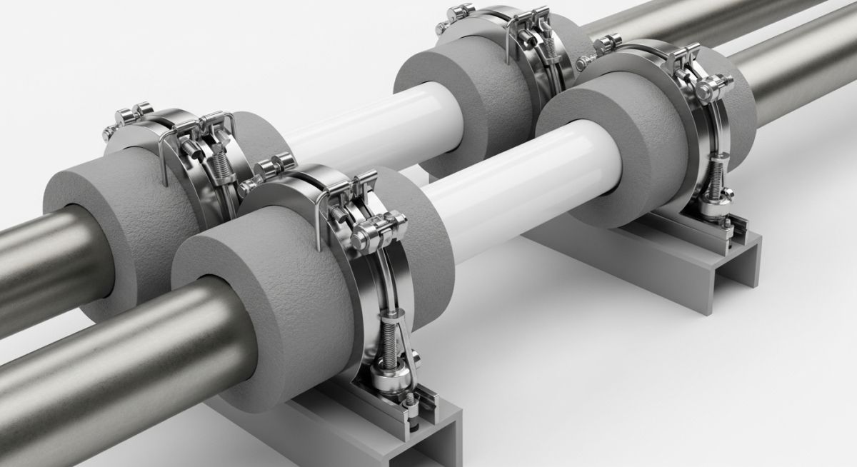
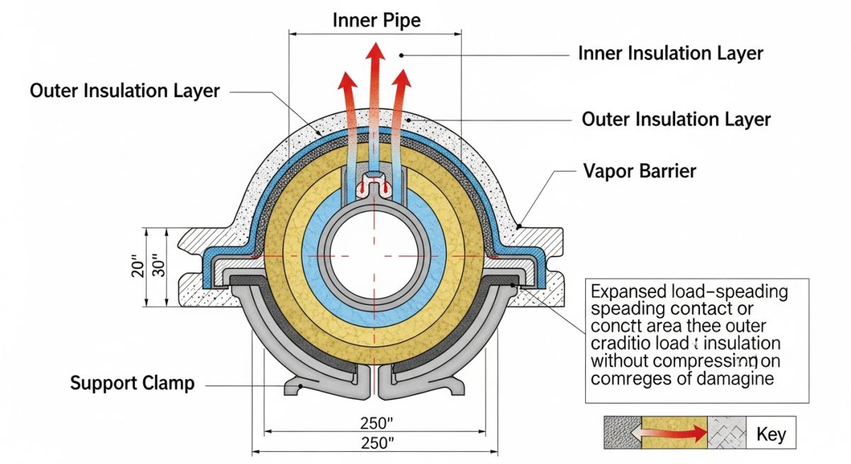
When we design supports for dual insulated piping, we are managing a complex load path. The weight of the inner carrier pipe, the process fluid, the inner insulation, the outer jacket, and the outer insulation must all be transferred to the structural steel support. This load must pass through the insulation material itself. Standard thermal insulation materials like low-density mineral wool or standard polyurethane foam have very low compressive strength. If subjected to direct support loads, they will crush, leading to a complete failure of the thermal barrier and the outer jacket.
To prevent this, we must use high-density, load-bearing insulation inserts at every support location. These inserts are typically made of high-density cellular glass, high-density polyurethane foam (HDPEF), or calcium silicate. The support design must distribute the load over a wide area using a metallic shield or cradle to keep the compressive stress well within the allowable limits of the insert material.
Never allow field contractors to substitute standard thermal insulation for high-density load-bearing inserts at support points. I have witnessed cases where standard polyurethane foam was used under a 12-inch line; within three weeks of commissioning, the foam crushed completely, causing the outer jacket to contact the steel beam, resulting in severe ice formation and a ruptured vapor barrier.
Calculating Compressive Stress on Insulation Inserts
To ensure the structural integrity of the support, we must calculate the localized compressive stress acting on the load-bearing insulation insert. The formula for calculating the average compressive stress is:
Let us walk through a practical engineering calculation. Consider a 10-inch nominal carrier pipe carrying a heavy liquid. The pipe is insulated with 2 inches of inner polyurethane foam, enclosed in a 14-inch outer containment jacket, which is further insulated with 2 inches of outer insulation, resulting in an 18-inch outer diameter at the support shield.
- Total weight of carrier pipe, fluid, jacket, and insulation: 120 kilograms per meter
- Support span: 6 meters
- Total load at the support (including a 1.2 safety factor for dynamic effects): 864 kilograms (approximately 8475 Newtons)
- Support shield width: 300 mm (0.3 meters)
- Outer diameter of the load-bearing insert: 457 mm (0.457 meters)
Using our formula, we calculate the projected area of the support:
Now, we calculate the compressive stress:
If we compare this result with the compressive strength of high-density cellular glass (typically 600 to 1000 kPa) or high-density polyurethane foam (typically 300 to 500 kPa), we see that our design has a safety factor of over 5. This is highly acceptable and complies fully with the stress limits outlined in ASME B31.3 and MSS SP-58.
Best Practices for Supporting Dual Insulated Piping Systems
To ensure the long-term reliability of these systems, several design rules must be strictly followed. First, the metallic shield surrounding the insulation insert must cover at least 180 degrees of the pipe circumference to distribute the load evenly and prevent localized pinching. For larger or heavier lines, a 360-degree shield is highly recommended.
Second, vapor barrier continuity is paramount. In cold or cryogenic service, any breach in the vapor barrier will allow moisture-laden air to penetrate the insulation. The moisture will freeze, expand, and destroy the insulation’s thermal properties, leading to severe corrosion of the carrier pipe. All joints between the load-bearing insert and the standard insulation must be sealed with a high-performance elastomeric vapor barrier mastic and reinforced with vapor barrier tape.
Recommended Support Spacing and Load Limits
The table below provides standard engineering guidelines for support spacing and maximum allowable loads for dual insulated piping systems. These values are based on a carbon steel carrier pipe, high-density cellular glass inserts, and a galvanized steel outer jacket, designed in accordance with ASME B31.3.
| Carrier Pipe Size (NPS) | Jacket Pipe Size (NPS) | Max Support Spacing (m) | Min Shield Length (mm) | Max Allowable Load (kN) |
|---|---|---|---|---|
| 3 | 6 | 3.5 | 250 | 3.2 |
| 4 | 8 | 4.2 | 300 | 4.8 |
| 6 | 10 | 5.0 | 300 | 7.5 |
| 8 | 12 | 5.8 | 350 | 11.2 |
| 10 | 14 | 6.5 | 400 | 15.8 |
| 12 | 16 | 7.2 | 450 | 21.0 |
This matrix maps the critical technical entities, structural acronyms, physical parameters, and their corresponding industry standards to ensure full compliance during the design phase.
| Entity / Acronym | Description | Key Physical Parameter | Standard Reference |
|---|---|---|---|
| HDPEF | High-Density Polyurethane Foam | Compressive Strength (300 to 500 kPa) | ASTM C591 |
| CG | Cellular Glass Insulation | Zero water vapor permeability | ASTM C552 |
| CUI | Corrosion Under Insulation | Wall thinning rate (mm/year) | API RP 583 |
| MSS SP-58 | Pipe Hangers and Supports Standard | Load rating and material selection | MSS SP-58 |
Field Verification Checklist for Support Installation
Before signing off on any dual insulated piping installation, I require my field inspectors to complete a rigorous physical audit. This checklist ensures that the supports are installed exactly as designed, preventing catastrophic thermal bridging and mechanical failures during plant startup.
Support Installation Audit Items
-
Verify Insert Material Density: Confirm that high-density load-bearing inserts (cellular glass or HDPEF) are installed at all support locations, not standard thermal insulation.
-
Check Shield Alignment: Ensure the metallic support shield is centered on the structural steel beam and provides a minimum of 180-degree coverage around the bottom of the pipe.
-
Inspect Vapor Barrier Seals: Visually inspect all mastic joints and vapor barrier tape. There must be zero gaps, pinholes, or wrinkles where moisture could enter.
-
Confirm Slide Plate Clearance: For sliding supports, verify that PTFE or bronze slide plates are clean, free of debris, and have sufficient travel clearance to accommodate thermal expansion.
-
Validate Bolt Torque: Ensure that clamp bolts are torqued to the manufacturer’s specified values to prevent crushing the insulation insert while maintaining structural grip.
Field Case Study: Real-World Application
The Problem: Cryogenic Line Support Failure
At a midstream LNG export terminal in Texas, a 12-inch cryogenic liquid line insulated with a dual-jacketed vacuum system began showing massive ice build-up at three consecutive pipe rack supports. Within months, the ice ball grew to over 200 kilograms, overloading the structural steel.
Upon investigation, I discovered that the installation contractor had omitted the high-density cellular glass inserts, placing standard low-density polyurethane foam directly under the support clamps. The weight of the pipe crushed the foam, causing the outer stainless steel jacket to make direct contact with the carbon steel support shoe, creating a severe thermal bridge.
The Outcome: Engineering Remediation
I led the engineering team to design a temporary hot-tap support system to hold the line while we replaced the failed supports. We installed 360-degree high-density cellular glass inserts with a compressive strength of 800 kPa, wrapped in a 3 mm thick galvanized steel shield.
We sealed all joints with a cryogenic-grade elastomeric mastic and applied a double layer of butyl rubber vapor barrier tape. After commissioning, thermal imaging confirmed zero heat leak, and the ice formation was completely eliminated, saving the operator from a catastrophic line rupture.
This case highlights why we must never compromise on material specifications or field inspection protocols. Proper engineering design is only half the battle; rigorous field quality control is what ultimately ensures plant safety.
Frequently Asked Engineering Questions
What is the primary purpose of using high-density inserts in dual insulated piping supports?
How do you prevent moisture ingress at the support locations?
Can cellular glass be used for high-temperature dual insulated systems?
What is the minimum recommended coverage angle for a pipe support shield?
How does differential thermal expansion affect support design?
Which industry codes govern the design of these specialized supports?

📚 Recommended Resources: supporting dual insulated piping
Read these Guides

Related posts:
![Aerial view of a BESS facility construction site showing earthwork grading, soil compaction, and site preparation for battery storage containers.]()
Earthwork Optimization for BESS Facilities: A Civil Engineering Guide
![Isometric view of a BESS site grading design showing battery containers, access roads, and perimeter drainage systems on a leveled site.]()
Essential Grading Design for BESS Sites: Engineering and Site Optimization
![Modern BESS facility site layout showing elevated concrete foundations and perimeter flood protection barriers for industrial safety.]()
Flood Protection for BESS Facilities: Engineering Design and Mitigation
![Utility-scale BESS container units installed on reinforced concrete slab foundations at a solar-plus-storage project site.]()
Essential Foundation Requirements for BESS Containers: A Technical Design Guide
![Aerial view of a utility-scale BESS facility showing containerized battery units, power conversion systems, and grid interconnection infrastructure in a flat, accessible site.]()
Strategic Site Selection Criteria for BESS Facilities Engineering Design
![Cross-section view of green hydrogen plant foundations showing soil strata and groundwater interaction for geotechnical risk assessment.]()
Managing Geotechnical Risks in Green Hydrogen Infrastructure Projects