Ultimate Guide to U-Bolt Pipe Support: Types, ASME Installation, and Field Applications
During a major refinery turnaround in 2021, I walked a 12-inch high-pressure steam line that had literally torn itself off its structural support beam. The culprit wasn’t an explosive process surge or a massive design miscalculation. It was a simple, over-tightened U-bolt pipe support. The field crew had cranked down on the hex nuts of what was supposed to be a free-sliding thermal guide, turning it into an accidental, rigid anchor. When the line heated up, the immense thermal expansion force had nowhere to go, destroying the structural steel panel.
In my experience on the field, U-bolts are the most misunderstood and abused commodities in any piping network. Piping designers treat them like simple hardware items, while field technicians often tighten them until the pipe wall physically deforms. This definitive engineering guide exposes exactly how to select, specify, and properly install a U-bolt pipe support so you can keep your systems operational and fully code-compliant.
What You Will Learn
- Critical mechanical design differences between a gripped and non-gripped U-bolt pipe support layout.
- Exact thread clearance settings required to guarantee proper piping thermal expansion movement.
- Standard material selection thresholds to stop galvanic corrosion in aggressive process plants.
- Step-by-step ASME B31.3 compliant torque methods to protect thin-walled stainless steel lines.
Featured Snippet Summary
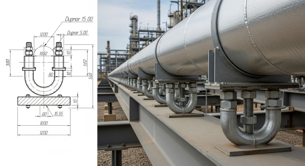
A U-bolt pipe support is a specialized U-shaped structural fastener featuring threaded ends designed to encircle, secure, guide, or anchor process piping to structural steel supports. Operating as either a free-sliding guide or a locked rigid anchor, it mitigates dynamic vibration, sustains deadweight loads, and controls thermal displacement across industrial piping networks.
Engineering Guide Roadmap
Interactive Field Engineering Knowledge Deck
Click any flashcard to flip and verify code compliance, standard references, and field-hardened insights from my years on the deck.
SGE Interactive Tool: U-Bolt Engineering Flashcards
Hover or tap each card below to instantly reveal core field deployment specifications, torque mechanics, and code requirements.
What is the primary difference between a gripped and non-gripped U-bolt pipe support?
Hover or Tap to Flip →A gripped U-bolt clamps the pipe rigidly to act as a 3D structural anchor, while a non-gripped configuration leaves a specific top-thread clearance to act as a sliding lateral guide.
Why do we use secondary backing locknuts on non-gripped U-bolt designs?
Hover or Tap to Flip →Backing locknuts mechanically lock the assembly position beneath the support beam, preventing the primary nut from spinning loose due to continuous pipeline vibration.
How does ASME B31.3 protect thin-walled stainless steel pipes from galvanic corrosion at U-bolts?
Hover or Tap to Flip →It requires the use of non-metallic isolation pads or thermoplastic liners like PTFE or neoprene to eliminate direct carbon steel to stainless steel contact.
What happens if a field technician over-tightens a thermal pipe guide U-bolt?
Hover or Tap to Flip →It turns the sliding guide into an accidental anchor, causing localized pipe wall buckling or structural steel failure during process thermal expansion.
Which code governs the material selection and loading limits of U-bolt pipe support components?
Hover or Tap to Flip →ASME B31.3 handles process design verification, while MSS SP-58 standardizes the physical manufacturing dimensions and material parameters.
When should you prefer a heavy-duty gripped U-bolt anchor over a traditional welded shoe?
Hover or Tap to Flip →Choose a gripped U-bolt when on-site hot work welding is banned due to live explosive hazards or when supporting non-weldable composite material lines.
What is the standard clearance for an ASME compliant non-gripped U-bolt guide?
Hover or Tap to Flip →A minimum physical air gap of 1.5 to 2.0 millimeters must be left between the top of the bare pipe wall and the inner radius of the U-bolt curve.
Why are standard carbon steel U-bolts hot-dip galvanized rather than electro-plated?
Hover or Tap to Flip →Hot-dip galvanizing produces a thicker layer of zinc iron alloy that survives harsh outdoor chemical plant elements far longer than thin electroplating.
How do shipping U-bolts protect piping systems during heavy open ocean transit?
Hover or Tap to Flip →They temporarily lock the line against rough hydrodynamic hull motions, preventing critical impact cracks at high-stress nozzle boundaries.
What is the purpose of an anti-vibration sleeve on a high-cycle gas U-bolt assembly?
Hover or Tap to Flip →The elastomer sleeve damps high-frequency acoustic vibrations, ensuring high cyclic stress does not crack or shear the structural threads.
Can you use a standard U-bolt on a vertical piping riser line?
Hover or Tap to Flip →Only if it is configured as a fully gripped anchor with an structural shear lug to stop the line from slipping straight down.
What failure mechanism occurs if U-bolt threads are stripped during maintenance torqueing?
Hover or Tap to Flip →Tensile overload yields the root thread profile, rendering the fastener incapable of retaining dynamic lateral wind or seismic loads.
What structural failure mechanism triggers when an engineering crew completely eliminates the top thread air gap on a non-gripped U-bolt guide?
Where must secondary backing locknuts be physically positioned on an ASME compliant non-gripped U-bolt configuration?
Which material combination directly violates standard process facility codes without protective non-metallic isolation?
What field action is critical regarding structural shipping U-bolts before initiating modular facility pre-commissioning?
What is a U-Bolt Pipe Support and How Does It Function?
In my thirty years of troubleshooting piping systems across heavy industrial units, I have learned that a U-bolt pipe support is much more than a generic piece of hardware bent into a letter shape. At its core, it is a highly specialized structural rod anchor or guide designed to fit snugly around the outer diameter of process piping. By routing the threaded legs through a structural steel beam, it links the processing line directly to the plant infrastructure.
But here is the catch: its core engineering function completely transforms based on thread engagement parameters. A single component can either isolate catastrophic dynamic forces or control thermal movements. It controls external piping deadweight loads, maintains structural integrity under seismic movements, and keeps structural alignment true.
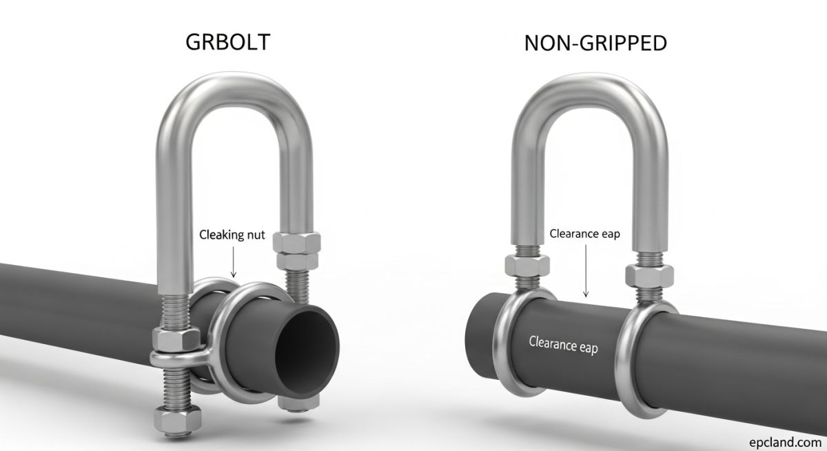
Structural Types: Gripped vs Non-Gripped U-Bolt Pipe Support
On the field, we actually split these configurations into two highly distinct mechanical classes. Mixing them up during structural modeling or field erection is the quickest route to an unscheduled facility shutdown.
CRITICAL FIELD WARNING: Standard isometric drawings do not always highlight nut configurations explicitly. I always instruct my inspection teams to check clearance tolerances manually before plant startup.
Non-Gripped U-Bolt: Functioning as a Piping Guide
The non-gripped U-bolt pipe support is intentionally configured to allow the process pipeline to slide along its axial path. We deliberately design a small air gap between the upper arc of the rod and the outside of the pipe casing. This lets the line expand thermally without imparting enormous physical loads onto structural frames.
The assembly uses dual locknuts located underneath the structural flange plate. This prevents the rod from pulling downward while ensuring the clear workspace above remains fully open and functional.
Gripped U-Bolt: Functioning as a Rigid Anchor
In complete contrast, a gripped configuration transforms the element into a completely rigid structural anchor. Here, the primary nuts on top of the cross beam are fully torqued down. This forces the inner steel radius of the loop into direct friction lock contact with the pipe casing wall.
This fully blocks movement along all three coordinate axes. In my experience, these are best utilized near sensitive equipment connections or to split massive cross-country pipeline corridors into predictable thermal loops.
Complete Course on Piping Engineering by Atul Singla on EPCLAND
Stop relying on guesswork or generic online charts. Join my field-tested, comprehensive engineering masterclass to fully dominate process piping designs, stress analysis pipelines, and structural support standards compliant with ASME B31.3.
Enroll in the Masterclass Now →Core Engineering Materials for U-Bolt Pipe Support Systems
Selecting the raw metallurgical specification for a U-bolt pipe support is not an afterthought. In my field practices, matching the support material properties directly to the parent process pipeline metallurgy is vital to control stress fatigue and galvanic reactions. According to MSS SP-58 standards, components are manufactured from standard carbon steel, low-alloy variants, or heavy stainless steel rods.
But here is the catch: raw carbon steel will fail rapidly in aggressive coastal environments or petrochemical units if it lacks defensive surface treatments. For temperatures under 200°C, I specify hot-dip galvanized coatings to achieve a resilient sacrificial zinc layer. When working with cryogenic or high-purity stainless steel lines, however, standard carbon steel elements are banned unless insulated by a thick thermoplastic or elastomer sleeve to stop carbon migration.
Field Applications of a U-Bolt Pipe Support
In the field, we position these versatile elements across dozens of plant layouts. They offer a highly cost-efficient alternative to massive welded support systems while remaining fully adjustable during commissioning stages.
Structural Restraint and Process Piping Stabilization
The most common assignment for a U-bolt pipe support is maintaining the structural alignment of horizontal lines across multi-tier piperacks. Operating as a sliding guide, it restrains the line from falling or twisting sideways due to wind loading, fluid surges, or seismic accelerations, while leaving the path clear for process-driven axial expansion.
Dynamic Load Mitigation During Pipe Shipping and Transit
When modular process skids are fabricated off-site and transported via deep-sea ocean cargo or heavy trucks, they experience extreme dynamic G-forces. Standard design guides require temporary shipping U-bolts to lock every single line rigid. This prevents vibration fatigue from cracking sensitive equipment nozzle connections before the module even arrives at the site.
| Design Attribute | Gripped Configuration (Anchor) | Non-Gripped Configuration (Guide) |
|---|---|---|
| Mechanical Role | Rigid 3D structural anchor block. | Axial sliding and thermal travel guide. |
| ASME Clearance Gap | 0.0 mm (Tight friction lock fit). | 1.5 mm to 2.0 mm clear top space. |
| Primary Code Focus | ASME B31.3 Section 321 static loads. | MSS SP-58 standard dimensional clearances. |
| Nut Arrangement | Torqued nuts above and below support steel. | Double locknuts locked under support steel only. |
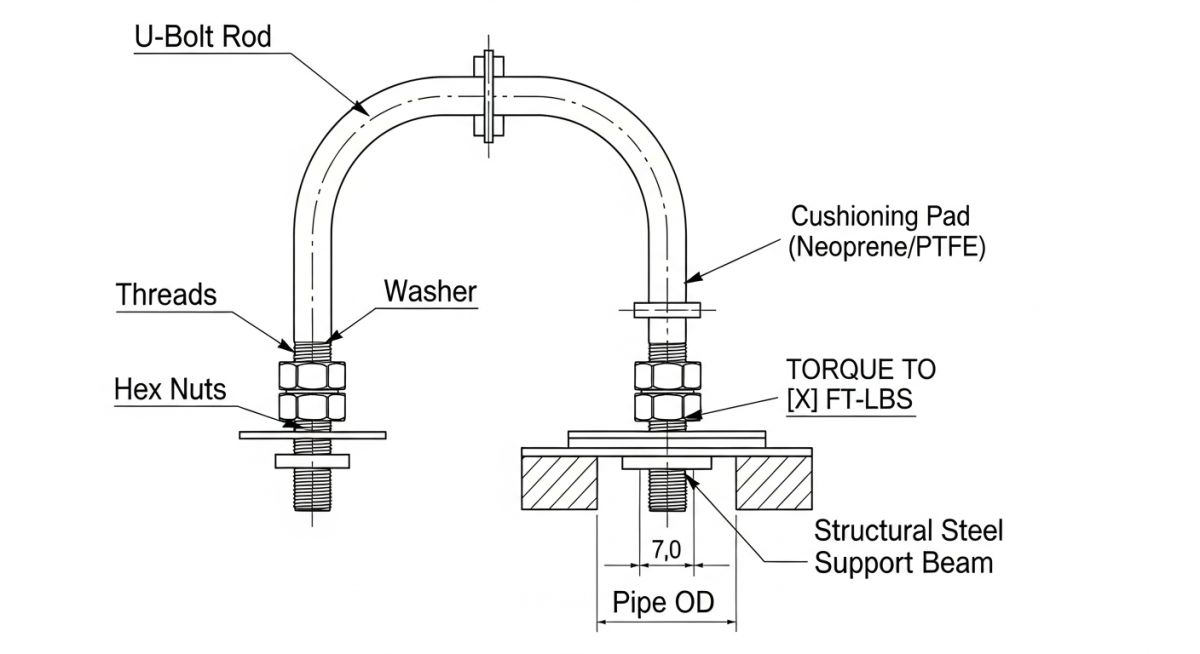
Standard Engineering Installation of a U-Bolt Pipe Support
Proper installation execution is exactly where basic construction field teams stumble. To achieve full compliance with ASME B31.3, the process must follow strict physical checks. For a sliding guide configuration, technicians must use a solid spacer tool or feeler gauge to ensure the top crown radius maintains its designated 1.5 mm clearance gap post-tightening.
Field Calculator: Recommended U-Bolt Rod Diameter
Based on standard industrial nominal pipe dimensions and structural deadweight design practices.
Field Hardened Lessons: Avoiding Common U-Bolt Failures
The Hydrocarbon Line Shear at the Coastal Gas Station
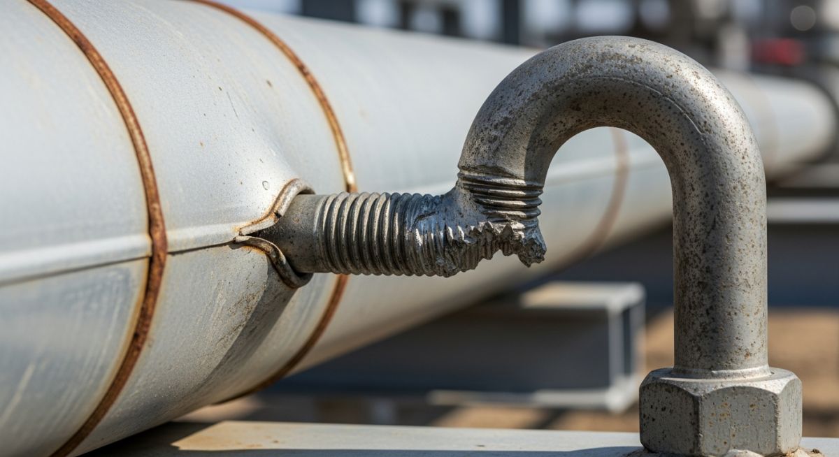
When I was working on a coastal offshore receiving module commissioning project back in 2018, the operations team faced an unexpected vibration fatigue crisis. A critical 6-inch hydrocarbon transfer loop was chewing through its support rods every few days. The structural assembly teams kept adding heavier hardware, moving from standard carbon steel rods up to high-tensile alloy steel configurations, but the components continued to snap across their thread roots.
I stepped onto the deck to lead a comprehensive structural physical audit. The root problem became immediately obvious the moment I examined the locked interfaces. The construction subcontractor was treating these guides like basic structural framing clamps. They were using high-torque impact guns to tighten the hex fasteners flat against the top structural cross beams, pulling the U-bolt pipe support flush against the bare pipe.
By compressing the steel rod tightly around the pipeline, they accidentally transformed a flexible thermal slide layout into a rigid, unintended 3D anchor lock. As the high-pressure gas streams pulsed through the system, the huge thermal stresses and dynamic forces accumulated directly at the bottom face of the structural beam steel plate. Since the pipe was restricted from moving forward or backward along its sliding plane, the intense energy was transferred entirely into shear loads across the rod threads.
I immediately ordered the crew to halt the torqueing guns. We scrapped the sheared elements and installed new, hot-dip galvanized units. This time, I stood on the platform and personally monitored the configuration. We backed off the upper nuts to leave a crisp 1.5 mm air space at the top crown radius, then jammed the double hex locknuts tightly beneath the structural steel flange plate. This restored the sliding axis, allowing the transfer loop to expand naturally. The structural failure pattern stopped immediately, and the unit has been running cleanly ever since.

Atul Singla
Founder of EPCLAND & Industrial Piping Specialist
I break down elite process engineering systems into practical field actions. With decades of international infrastructure and plant turnaround execution experience, my mission is to eliminate field errors and help industrial designers master global engineering standards.
Frequently Asked Questions: U-Bolt Pipe Support Systems
Direct engineering answers to the most common technical questions encountered during process plant fabrication and structural engineering inspections.
What is the standard clearance for an ASME compliant non-gripped U-bolt guide?
Can I use standard carbon steel U-bolts directly on a stainless steel process line?
Why do we require dual backing locknuts on the bottom side of the support beams?
When should a grabbed configuration be preferred over a standard welded shoe?
How do hot-dip galvanized finishes compare to electroplated threads on the field?
What happens if a field technician over-tightens a thermal sliding guide?
📚 Recommended Resources: U-bolt pipe support


Related posts:
![Outdoor pipeline block valve station with large isolation valves and actuators.]()
What are Pipeline Block Valves and How to Design Stations
![3D CAD model of an industrial process plant showing equipment clearances and access platforms.]()
A Guide to Plant Clearances and Access Requirements
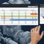
![Engineering technical bid evaluation spreadsheet comparing vendor specifications and compliance metrics.]()
How to Master Technical Bid Evaluation for Complex Engineering Procurement
![Large-diameter steel pipes with protective blue anti-corrosive epoxy coating stacked in an industrial facility.]()
Protecting Steel Pipes with Anti-Corrosive Steel Pipe Coatings
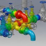
![3D CAD model of industrial piping showing stress intensification factor heatmaps at elbows and tees.]()
Why Stress Intensification Factor in Piping Dictates Fatigue Life
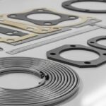
![A collection of different industrial pipe flange gaskets on a workbench]()
How to Select the Best Pipe Flange Gaskets for Piping Systems