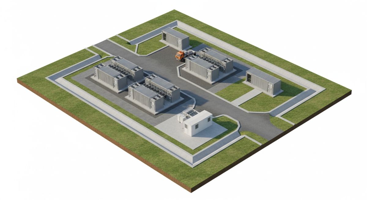
Grading Design for BESS Sites: Engineering Best Practices
In my two decades of managing industrial site development, I have observed that the success of a Battery Energy Storage System (BESS) project often hinges on the quality of the initial grading design. Unlike traditional substations, BESS sites require precise elevation control to mitigate thermal runaway risks and ensure that sensitive power electronics remain protected from moisture ingress.
Effective grading is not merely about moving dirt; it is about balancing the cut-and-fill volumes while adhering to stringent geotechnical requirements. When I approach a new site, I prioritize the interface between the container foundation and the finished grade, as even minor settlement can compromise the structural integrity of the battery racks.
Key Takeaways for BESS Grading:
- Achieve a minimum 1% slope away from container foundations to prevent ponding.
- Optimize earthwork by utilizing on-site soil stabilization techniques to reduce import costs.
- Integrate fire suppression access requirements directly into the primary site grading plan.
- Ensure compliance with local flood zone regulations and NFPA 855 standards.
Technical Fundamentals of BESS Site Grading Design
BESS Site Grading Design: The technical application of civil engineering principles to establish site topography that supports heavy battery containers, facilitates rapid emergency response, and manages hydrological runoff in accordance with NFPA 855 and local building codes.
When designing the grading for a BESS facility, I focus heavily on the “pad-to-grade” interface. The container foundation, typically a concrete slab-on-grade or a pier-and-beam system, must be elevated above the 100-year flood elevation. My standard practice involves calculating the differential settlement potential of the subgrade, especially when dealing with expansive clays or loose fill materials.
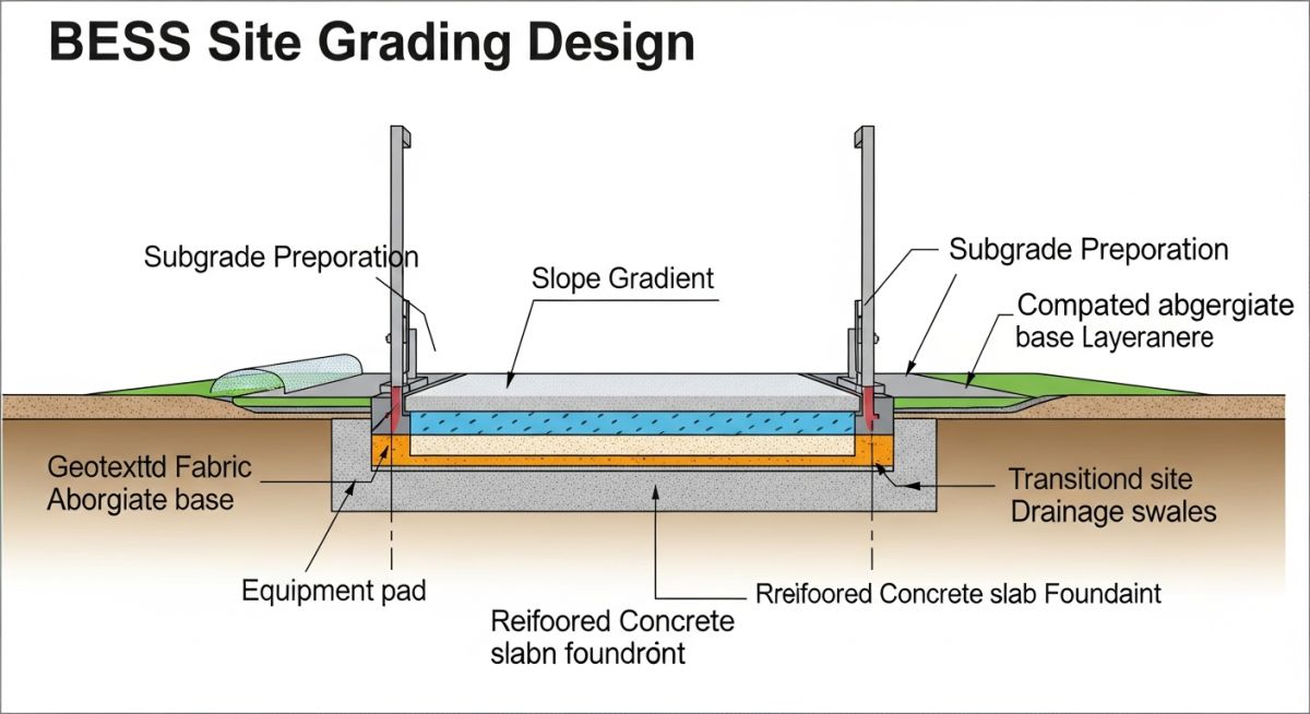
Earthwork Optimization and Soil Mechanics
To optimize earthwork, I perform a mass-haul analysis to minimize the need for off-site soil disposal or import. The goal is to achieve a balanced site where the cut volume equals the fill volume, adjusted for the shrinkage factor of the native soil. I utilize ASTM D698 for standard proctor density testing to ensure the subgrade can support the concentrated loads of the BESS containers, which often exceed 50,000 lbs per unit.
Field Warning: Differential Settlement
In my experience, uneven compaction is the primary cause of container door misalignment and internal rack stress. Always specify a minimum of 95% Modified Proctor Density for the top 12 inches of subgrade beneath the container footprint. If the site requires significant fill, utilize geogrid reinforcement to distribute the load and bridge potential soft spots in the native soil.
Drainage Design and Hydrological Control
Drainage design for BESS sites is critical because water is the enemy of battery longevity. I design the site with a primary drainage slope of 1% to 2% away from the containers, directing runoff into a perimeter swale or a detention basin. The design must account for the “time of concentration” to ensure that peak flow rates do not exceed the capacity of the downstream municipal storm sewer system.
I also incorporate an oil-water separator if the site includes large transformers, ensuring that any potential dielectric fluid leaks are captured before they reach the storm drainage system. This is a requirement under SPCC (Spill Prevention, Control, and Countermeasure) regulations. By integrating these features into the grading plan, we avoid costly retrofits during the construction phase.
Grading Design Trade-offs: The strategic evaluation of site development methods that balance initial capital expenditure against long-term operational reliability and maintenance requirements for energy storage infrastructure.
Advantages
- Improved structural longevity by preventing moisture-related foundation degradation.
- Reduced long-term maintenance costs through effective erosion control and drainage.
- Enhanced site safety by ensuring clear, level access for emergency response vehicles.
- Optimized earthwork reduces the carbon footprint associated with soil transport.
- Better compliance with environmental regulations regarding runoff and spill containment.
Disadvantages
- Higher initial engineering and surveying costs for precise site grading.
- Extended permitting timelines due to complex stormwater management requirements.
- Potential for significant cost overruns if geotechnical reports are inaccurate.
- Increased site footprint requirements to accommodate necessary drainage swales and basins.
- Strict adherence to slope requirements may limit the usable area for battery arrays.
BESS Infrastructure Deployment: The practical implementation of site grading strategies across diverse industrial and utility-scale environments to ensure operational continuity and regulatory compliance.
Utility-Scale Solar Integration
In large-scale solar farms, BESS grading must align with the existing topography of the PV array to minimize massive earth movement. I focus on creating tiered pads that follow the natural contours while maintaining the strict 1% drainage requirement for the battery containers.
Urban Peak Shaving Facilities
When deploying BESS in space-constrained urban environments, grading design often involves retaining walls and complex sub-surface drainage systems. These sites require precise vertical control to maximize the number of containers within a limited footprint while ensuring fire department access.
Industrial Microgrid Resilience
For industrial manufacturing plants, the BESS site is often located near existing heavy infrastructure. Grading here must account for vibration isolation and the proximity to high-voltage switchgear, requiring a stable, well-drained subgrade that prevents any shifting of the container-to-transformer bus connections.
Remote Off-Grid Mining Operations
In remote mining applications, the grading design must be self-sufficient, often utilizing local materials for base stabilization. I prioritize robust drainage channels that can handle extreme weather events, as these sites lack the luxury of municipal storm sewer connectivity.
Effective BESS site grading requires a precise balance between geotechnical stability and hydraulic performance. In my experience, the following table outlines the critical design thresholds that govern the transition from raw land to a functional battery storage facility. These values are derived from standard ASCE guidelines and typical NFPA 855 requirements for fire safety and equipment access.
Engineers must prioritize these parameters during the preliminary design phase to avoid costly re-grading or drainage retrofits later in the project lifecycle. Note that local jurisdictional requirements may impose stricter limits, particularly regarding maximum slope gradients for heavy transport vehicles carrying lithium-ion battery containers.
| Design Parameter | Recommended Range | Engineering Rationale |
|---|---|---|
| Pad Longitudinal Slope | 0.5% to 1.0% | Ensures positive drainage while maintaining container levelness. |
| Access Road Cross-Slope | 2.0% to 3.0% | Prevents water ponding on critical transport routes. |
| Max Embankment Slope | 3H:1V to 4H:1V | Maintains soil stability and facilitates vegetation growth. |
| Minimum Freeboard | 1.0 ft (0.3 m) | Required for 100-year storm event flood protection. |
By adhering to these ranges, you ensure that the site remains resilient against erosion and structural settlement. Always verify these values against the specific geotechnical report for your site, as soil bearing capacity often dictates the final grading strategy.
The following matrix maps the core technical entities involved in BESS site development to their respective industry standards and physical parameters. Understanding these relationships is vital for cross-disciplinary coordination between civil, electrical, and structural engineering teams.
Each entity represents a critical node in the site development process, from initial earthwork calculations to final drainage certification. By maintaining this mapping, project managers can ensure that all design components comply with the necessary regulatory frameworks and safety protocols.
| Entity | Standard Reference | Primary Function |
|---|---|---|
| BESS Container Pad | ASCE 7 | Structural support and seismic load distribution. |
| Stormwater Basin | EPA NPDES | Runoff attenuation and sediment control. |
| Access Roadway | AASHTO | Heavy equipment ingress and egress. |
| Site Perimeter Fence | NFPA 855 | Security and fire safety clearance zones. |
This matrix serves as a foundational reference for site design reviews. When discrepancies arise during the permitting process, referring back to these standard-linked entities helps clarify the design intent and regulatory requirements for stakeholders.
Before finalizing any grading plan, I conduct a rigorous site verification process to ensure that the theoretical design aligns with the physical reality of the terrain. This checklist is designed to catch common oversights that lead to drainage failures or structural settlement in BESS installations.
-
Geotechnical Validation: Confirm that the soil bearing capacity matches the assumed values used in the pad design calculations per ASTM D2487. -
Drainage Path Continuity: Verify that all swales and culverts are free of obstructions and that the final discharge point complies with local NPDES permits. -
Clearance Zones: Ensure that the grading plan maintains the required fire safety separation distances between containers as specified in NFPA 855. -
Access Road Turning Radii: Validate that the road geometry accommodates the largest delivery vehicle expected during the construction and maintenance phases. -
Erosion Control Measures: Confirm that silt fences and sediment basins are installed according to the Stormwater Pollution Prevention Plan (SWPPP).
By systematically checking these items, you mitigate the risk of project delays and ensure long-term site viability. In my experience, the most successful projects are those where the civil design team maintains constant communication with the electrical and structural leads throughout the site preparation phase.
Field Case Study: Real-World Application
The Challenge: Unforeseen Subsurface Water Accumulation
During the construction of a 50MW BESS facility, we encountered significant groundwater seepage that threatened the stability of the primary container pads.
- Inaccurate initial geotechnical survey failing to identify a perched water table.
- Inadequate sub-drainage design for the specific soil permeability encountered.
- Rapid onset of seasonal rainfall exacerbating the saturation of the subgrade.
The Outcome: Successful Remediation and Site Stabilization
We implemented a comprehensive subsurface drainage system that successfully stabilized the site and allowed construction to proceed on schedule.
- Installation of a perforated underdrain network connected to a central detention basin.
- Replacement of saturated subgrade with engineered structural fill to improve bearing capacity.
- Implementation of a real-time piezometer monitoring system to track groundwater levels.
My recommendation for similar projects is to always perform a secondary geotechnical investigation if the site shows any signs of poor drainage or high water tables during the initial clearing phase. Proactive sub-drainage is significantly cheaper than retrofitting a foundation after the containers are installed.
Frequently Asked Engineering Questions
What is the primary purpose of site grading for BESS?
- Ensuring structural integrity by preventing differential settlement of heavy battery containers.
- Managing stormwater runoff to protect electrical components from water damage.
- Providing safe access for heavy transport vehicles during the installation and maintenance phases.
- Complying with NFPA 855 fire safety requirements regarding site clearance and access.
How do you calculate the required pad slope?
- Typically, a slope of 0.5% to 1.0% is sufficient to shed water without requiring complex leveling shims for the containers.
- The calculation must account for the total length of the pad and the location of the drainage collection points.
- Engineers use the rise over run formula to ensure the slope remains within the manufacturer’s tolerance, which is often as tight as 1/8 inch per foot.
- Always verify the final slope against the site’s overall drainage plan to ensure water is directed away from the equipment toward designated swales.
What are the flood protection requirements for BESS?
- The finished floor elevation of the battery containers is typically set at least one foot above the 100-year flood elevation.
- Site grading must include detention basins designed to handle the peak runoff from a 100-year storm event.
- Engineers must consult local FEMA flood maps to determine the base flood elevation for the project site.
- In high-risk areas, additional measures such as perimeter berms or elevated pad foundations may be necessary to ensure compliance.
How do you optimize earthwork for BESS sites?
- The primary goal is to achieve a balanced site where the volume of cut equals the volume of fill, eliminating the need for off-site soil transport.
- Using software like Civil 3D allows engineers to iterate on the site grading plan to find the most efficient balance.
- Adjusting the site layout to follow the natural contours of the land can significantly reduce the amount of earth that needs to be moved.
- Proper compaction testing is required to ensure that the fill material provides the necessary bearing capacity for the heavy battery containers.
What are the access road design standards?
- Road width and turning radii must be calculated based on the specific dimensions of the battery container delivery trucks.
- Pavement design should account for the heavy axle loads associated with these vehicles, often requiring a robust sub-base and aggregate layer.
- Cross-slopes are typically kept between 2% and 3% to ensure effective drainage while maintaining vehicle stability.
- All road designs must comply with local fire department access requirements, which often dictate minimum widths and load-bearing capacities.
How does soil type affect grading design?
- Clay-heavy soils may require more extensive sub-drainage and soil stabilization techniques to prevent settlement.
- Sandy soils provide better drainage but may require more robust erosion control measures during the construction phase.
- Geotechnical reports provide the necessary data on soil bearing capacity, which is used to determine the thickness of the pad foundation.
- Understanding the soil’s expansion and contraction properties is vital for preventing cracks in the concrete pads over the life of the BESS facility.
Complete Course on
Piping Engineering
Check Now
Key Features
- 125+ Hours Content
- 500+ Recorded Lectures
- 20+ Years Exp.
- Lifetime Access
Coverage
- Codes & Standards
- Layouts & Design
- Material Eng.
- Stress Analysis