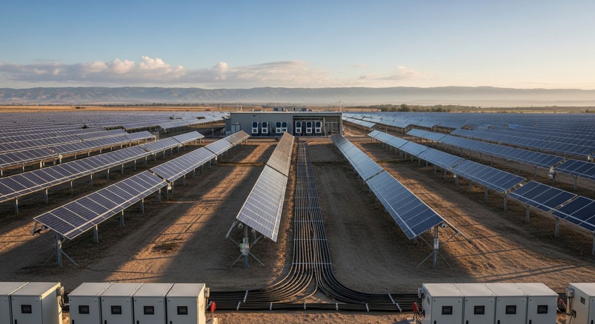
Solar Photovoltaic System Explained: Design and Engineering Principles
In my two decades of experience across industrial infrastructure, I have observed that the transition to renewable energy relies heavily on the robust design of the Solar Photovoltaic (PV) system. A PV system is not merely a collection of panels; it is a sophisticated power plant that requires precise electrical, mechanical, and thermal integration to ensure longevity and efficiency.
Whether you are designing a small-scale commercial array or a massive utility-scale farm, understanding the physics of the photovoltaic effect and the subsequent power conditioning is paramount. This guide dissects the core components, from the semiconductor material to the grid-tie inverter, providing the technical clarity needed for successful project execution.
Key Takeaways
- Master the fundamental energy conversion process from photon to electron flow.
- Understand the critical role of Maximum Power Point Tracking (MPPT) in system efficiency.
- Learn the essential standards for structural mounting and electrical safety.
- Identify performance factors that dictate the Levelized Cost of Energy (LCOE).
Solar Photovoltaic System Technical Deep-Dive
Solar Photovoltaic System Engineering: The systematic arrangement of PV modules, inverters, and balance-of-system components designed to maximize energy yield while adhering to strict electrical safety and structural integrity codes.
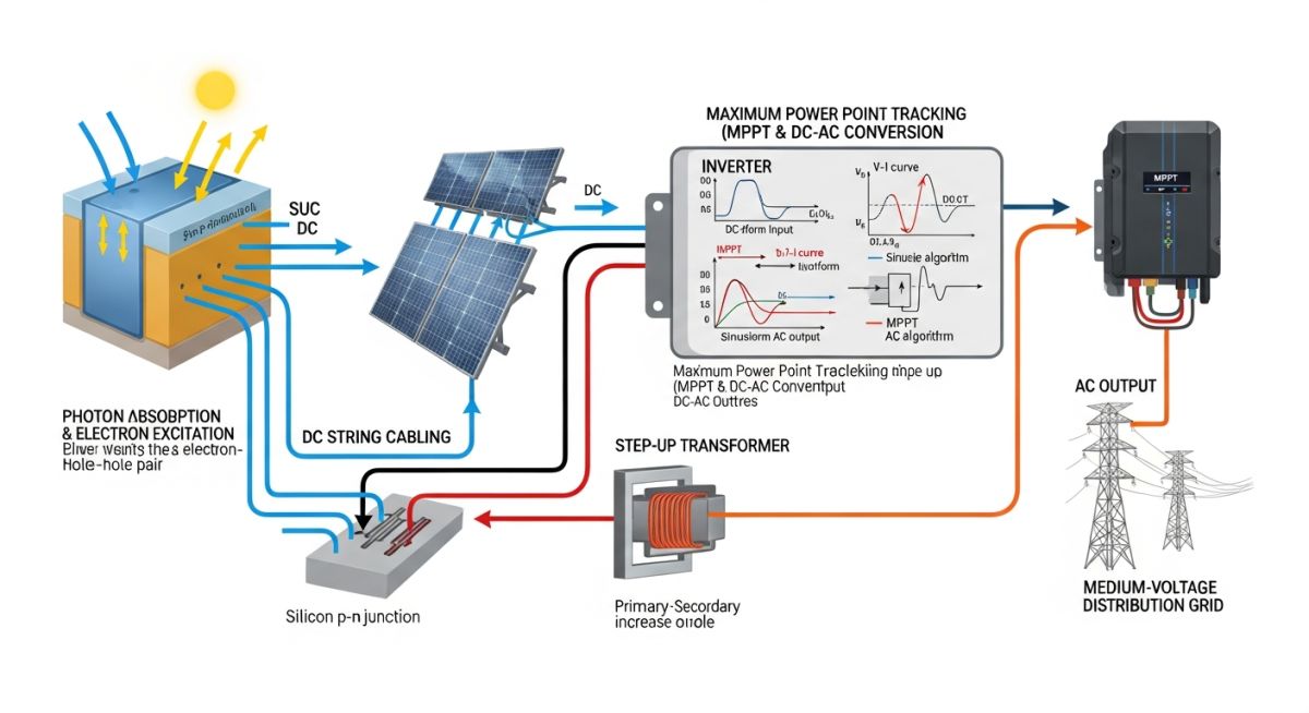
The core of any Solar Photovoltaic System is the semiconductor junction, typically silicon-based, which facilitates the photovoltaic effect. When photons strike the cell, they excite electrons, creating a potential difference. In my practice, I emphasize that the efficiency of this conversion is dictated by the bandgap of the material and the spectral response of the cell, as defined in ASTM E1036.
Energy Conversion and MPPT Logic
The DC output from a PV string is inherently unstable due to fluctuating irradiance and temperature. To optimize this, we utilize Maximum Power Point Tracking (MPPT) algorithms within the inverter. The power output P is the product of voltage V and current I. Since the I-V curve of a PV module is non-linear, the MPPT controller continuously adjusts the load to operate at the knee of the curve where power is maximized.
Field Warning: Thermal Derating
Never ignore the temperature coefficient of the PV modules. As cell temperature increases, the open-circuit voltage (Voc) drops significantly. In high-ambient-temperature environments, this can lead to a reduction in string voltage below the inverter’s minimum MPPT window, causing system downtime. Always calculate the worst-case voltage at the lowest expected ambient temperature to ensure compliance with NEC Article 690.
Structural and Electrical Integration
Structural design must account for wind loads and snow loads as per ASCE 7. I have seen many projects fail due to inadequate corrosion protection on mounting hardware in coastal environments. Furthermore, the electrical balance-of-system (BOS) includes combiner boxes, DC disconnects, and surge protection devices (SPDs). These components must be rated for the maximum system voltage, which is often 1500V DC in modern utility-scale designs.
The conversion process concludes at the inverter, where DC is inverted to AC. The efficiency of this stage is measured by the weighted CEC efficiency. For grid-tied systems, the inverter must also provide anti-islanding protection to prevent back-feeding the grid during maintenance, a requirement strictly enforced by IEEE 1547.
Solar Photovoltaic System Performance: A critical evaluation of the operational benefits and technical limitations inherent in current semiconductor-based solar energy harvesting technologies.
Advantages
- Minimal operational expenditure (OPEX) due to lack of moving parts.
- Modular scalability allows for incremental capacity expansion.
- High reliability with typical 25-year performance warranties.
- Zero emissions during the energy generation phase.
- Rapid deployment compared to conventional thermal power plants.
Disadvantages
- Intermittency requires energy storage or grid-balancing solutions.
- High initial capital expenditure (CAPEX) for high-efficiency modules.
- Large land footprint requirements for utility-scale installations.
- Efficiency degradation over time due to environmental exposure.
- Complexity in managing DC-side arc fault detection and mitigation.
Solar Photovoltaic System Deployment: Diverse industrial and commercial implementations ranging from decentralized microgrids to large-scale utility power generation facilities.
Utility-Scale Power Generation
These installations function as primary power plants, injecting multi-megawatt capacity directly into the transmission grid. They utilize central inverters and high-voltage transformers to minimize transmission losses, requiring sophisticated SCADA systems for real-time grid frequency and voltage regulation.
Industrial Facility Decarbonization
Manufacturing plants integrate rooftop or carport PV arrays to offset high daytime energy consumption. This application focuses on peak-shaving, where the solar output reduces the facility’s demand charges during peak utility pricing hours, significantly improving the project’s internal rate of return.
Remote Microgrid Electrification
In off-grid industrial sites, such as mining operations or remote pumping stations, PV systems are coupled with battery energy storage systems (BESS). This hybrid configuration ensures continuous power availability, reducing reliance on expensive and carbon-intensive diesel generator sets.
Agricultural Irrigation Systems
Solar-powered pumping systems utilize variable frequency drives (VFDs) to match the pump motor speed to the available solar irradiance. This eliminates the need for grid connection in remote fields, providing a sustainable water management solution for large-scale agricultural operations.
When evaluating the efficiency of a Solar Photovoltaic System, engineers must look beyond nominal power ratings. The performance of these systems is heavily dictated by environmental variables and the specific semiconductor material properties inherent to the cell technology. In my experience, the most critical metrics involve understanding how temperature coefficients and irradiance levels interact with the IEC 61215 standards for terrestrial PV modules.
The following table outlines the typical performance characteristics for common cell technologies. Note that while monocrystalline silicon remains the industry standard for high-efficiency residential and commercial applications, thin-film technologies often provide superior performance in high-temperature environments due to lower temperature coefficients. Always verify these values against the manufacturer’s datasheet, as variations in manufacturing processes can lead to significant deviations in the final energy yield calculations.
| Technology Type | Efficiency Range | Temp Coefficient | Degradation Rate |
|---|---|---|---|
| Monocrystalline Silicon | 18% – 24% | -0.35%/C | 0.5% per year |
| Polycrystalline Silicon | 15% – 18% | -0.40%/C | 0.7% per year |
| Thin-Film (CdTe) | 12% – 16% | -0.25%/C | 0.6% per year |
Engineers should prioritize the temperature coefficient when designing for desert or tropical climates. A lower negative value indicates that the module loses less power as the ambient temperature rises, which is a vital consideration for maintaining the internal rate of return (IRR) over the project’s 25-year lifespan.
The successful deployment of a Solar Photovoltaic System requires a deep understanding of the interconnected electrical and mechanical entities. From the microscopic level of the P-N junction to the macroscopic level of the grid-tied inverter, each component must be mapped to specific international standards to ensure safety, reliability, and optimal energy conversion efficiency.
This matrix provides a technical overview of the primary entities involved in PV system design. By aligning these components with their respective standards, such as ASME-related structural requirements for mounting and IEEE 1547 for grid interconnection, engineers can mitigate risks associated with system failure or non-compliance. Use this as a reference for your Bill of Materials (BOM) and technical specifications documentation.
| Entity | Function | Standard Reference |
|---|---|---|
| PV Module | DC Power Generation | IEC 61215 |
| Inverter | DC to AC Conversion | IEEE 1547 |
| Mounting Structure | Mechanical Support | ASCE 7-16 |
| Charge Controller | Battery Management | UL 1741 |
Always ensure that the selected components are compatible with the local grid voltage and frequency requirements. Mismatched components are the leading cause of premature inverter failure and reduced system uptime in large-scale utility projects.
Before finalizing the design of any Solar Photovoltaic System, a rigorous site verification process is mandatory. My experience has shown that overlooking site-specific environmental factors often leads to significant performance degradation and increased maintenance costs. This checklist serves as a baseline for your pre-installation audit, ensuring that all structural, electrical, and environmental variables are accounted for before the first bolt is tightened.
-
[ ]
Shading Analysis: Perform a comprehensive 360-degree horizon survey to identify potential shading from trees, buildings, or future infrastructure. Use a solar pathfinder tool to map shading patterns across all four seasons. -
[ ]
Structural Integrity: Verify that the roof or ground mounting surface meets the load-bearing requirements defined in ASCE 7-16 for wind and snow loads. -
[ ]
Electrical Interconnection: Confirm the capacity of the existing electrical service panel and the distance to the point of common coupling (PCC) to minimize voltage drop. -
[ ]
Soil Resistivity: For ground-mounted systems, conduct soil resistivity testing to ensure the grounding system meets the requirements of NFPA 70 (NEC). -
[ ]
Environmental Exposure: Assess the site for high salt mist, dust, or industrial pollutants that may necessitate specialized module coatings or more frequent cleaning schedules.
Document every finding in a formal site survey report. If any of these parameters fall outside the design specifications, you must adjust the system configuration—such as increasing the tilt angle or selecting modules with higher durability ratings—before proceeding to the procurement phase.
Problem: High-Temperature Performance Degradation
A 500kW commercial rooftop project in a desert climate experienced a 15% drop in expected energy yield during peak summer months due to excessive module heating.
- Inadequate ventilation gap between modules and the roof surface.
- Selection of modules with a high negative temperature coefficient.
- Lack of reflective roofing material to reduce ambient heat absorption.
- Inverter placement in an unshaded, poorly ventilated enclosure.
Outcome: Optimized Thermal Management Strategy
By retrofitting the system with improved airflow and thermal management, the project recovered 12% of the lost energy yield within the first year.
- Increased mounting height to 300mm to facilitate natural convection.
- Applied high-albedo white roof coating to lower ambient temperatures.
- Relocated inverters to a climate-controlled, shaded service room.
- Implemented a real-time monitoring system to track module temperature vs. output.
My recommendation for similar projects is to always conduct a thermal simulation during the design phase. Never assume that standard mounting practices will suffice in extreme climates; proactive thermal management is the most cost-effective way to protect your long-term energy production.
How does the P-N junction facilitate energy conversion?
- The electric field at the junction forces electrons toward the N-type layer and holes toward the P-type layer.
- This separation creates a potential difference, or voltage, across the cell terminals.
- The process is governed by the quantum mechanical properties of the semiconductor bandgap.
- Without this junction, the excited electrons would simply recombine, releasing energy as heat rather than electricity.
What is the role of the inverter in a PV system?
- Maximum Power Point Tracking (MPPT) ensures the system operates at the peak of the I-V curve.
- Grid synchronization ensures the AC output matches the frequency and phase of the utility grid.
- Safety features like anti-islanding prevent the system from energizing the grid during a power outage.
- Data logging provides real-time performance metrics for remote monitoring and maintenance.
How do temperature coefficients affect system design?
- Voltage is inversely proportional to temperature; as the cell heats up, the open-circuit voltage drops significantly.
- Current increases slightly with temperature, but this gain is insufficient to offset the voltage loss.
- Engineers must calculate the worst-case voltage at the lowest expected ambient temperature to avoid exceeding inverter input limits.
- Proper thermal design is essential to maintain the system’s efficiency throughout the hottest months of the year.
Why is shading analysis critical for system performance?
- Bypass diodes are used to mitigate shading, but they effectively remove the shaded portion of the string from production.
- Even partial shading of a single cell can trigger a bypass diode, resulting in a disproportionate loss of power.
- Advanced solutions like microinverters or DC optimizers allow for module-level power management, minimizing the impact of localized shading.
- A thorough shading analysis is the only way to accurately predict the annual energy yield and ensure the project’s financial viability.
What are the primary differences between grid-tied and off-grid systems?
- Grid-tied systems export excess energy to the utility grid, often utilizing net metering to offset electricity costs.
- Off-grid systems require a battery bank to store energy for use during non-sunlight hours, significantly increasing the initial capital expenditure.
- Hybrid systems combine both, offering the reliability of grid connection with the security of battery backup.
- Each configuration requires different inverter technology and control logic to manage power flow and safety protocols.
How do international standards ensure system safety?
- IEC 61215 and IEC 61730 define the rigorous testing required for module durability and safety.
- IEEE 1547 sets the requirements for grid interconnection, ensuring that PV systems do not destabilize the grid.
- NFPA 70 (NEC) provides the electrical installation guidelines that prevent fire hazards and ensure worker safety.
- Compliance with these standards is not just a regulatory requirement; it is a fundamental engineering practice that protects the asset and the public.
Complete Course on
Piping Engineering
Check Now
Key Features
- 125+ Hours Content
- 500+ Recorded Lectures
- 20+ Years Exp.
- Lifetime Access
Coverage
- Codes & Standards
- Layouts & Design
- Material Eng.
- Stress Analysis