Table of Contents
Mastering Pipe Thickness Calculation for High Pressure Piping Systems
In my 20 years of managing piping stress analysis and mechanical integrity for massive petrochemical complexes, I have seen how a single misplaced decimal in a wall thickness calculation can lead to catastrophic field failures. Calculating the correct pipe wall thickness is not just about plugging numbers into a software program; it is about understanding the physical limits of the steel, the corrosive nature of the fluid, and the strict safety margins mandated by international codes.
When designing high-pressure, high-temperature systems, we must balance safety, cost, and constructability. Over-designing leads to excessive material costs and structural support challenges, while under-designing risks catastrophic rupture. This guide walks you through the exact mathematical steps, code requirements, and practical field considerations I use daily to ensure piping safety and pressure containment.
Key Engineering Takeaways
- Understand the exact ASME B31.3 formula variables to avoid over-designing or under-designing.
- Always account for the standard 12.5% mill tolerance during nominal pipe schedule selection.
- Factor in corrosion and erosion allowances based on fluid characteristics and design life.
- Select the correct weld joint quality factors and temperature-dependent Y coefficients.
- Verify physical wall thickness on-site using non-destructive ultrasonic testing.
How to Perform Pipe Thickness Calculation Accurately
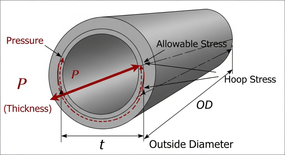
To determine the minimum required wall thickness for a straight pipe under internal pressure, we turn to the industry-standard code: ASME B31.3 Section 304.1.2. The fundamental equation used for pipes where the thickness is less than one-sixth of the outside diameter is written as follows:
Where each variable represents a specific physical or material parameter that must be selected with extreme care:
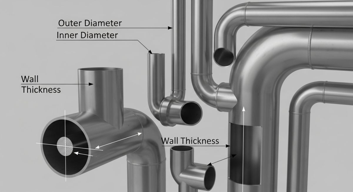
- t = Pressure design thickness (inches or millimeters). This is the raw thickness required solely to contain the internal pressure.
- P = Internal design gage pressure (psi or MPa). This value must include any transient pressure surges if they exceed the design pressure by more than 10% for short durations.
- D = Outside diameter of the pipe (inches or millimeters) as specified in standards like ASME B36.10M.
- S = Allowable stress value for the material at the design temperature (psi or MPa). These values are obtained directly from ASME B31.3 Appendix A, Table A-1.
- E = Quality factor. This factor accounts for the manufacturing method of the pipe. For seamless pipes, E is 1.00. For electric resistance welded (ERW) pipes, E is typically 0.85.
- W = Weld joint strength reduction factor. This factor accounts for the reduction in strength of welded joints at elevated temperatures where creep occurs. For temperatures below 510 degrees Celsius (950 degrees Fahrenheit), W is typically 1.00.
- Y = Coefficient from Table 304.1.1. This coefficient accounts for the non-linear stress distribution across the pipe wall in thick-walled pipes and varies based on material type and temperature.
Accounting for Mechanical and Corrosion Allowances
The pressure design thickness (t) is only the starting point. In my practice, I always emphasize that a pipe in service does not remain in its pristine, brand-new condition. It is subjected to internal corrosion, external erosion, and mechanical wear. Therefore, we must calculate the minimum required thickness ™ by adding these allowances:
Where c is the sum of mechanical allowances (such as thread depth or groove depth for mechanical couplings) plus corrosion and erosion allowances. For carbon steel pipes in non-corrosive utility service, a standard corrosion allowance of 1.5 mm is common. For highly corrosive sour gas or acid services, this allowance can jump to 3.0 mm or even 6.0 mm.
Never ignore the 12.5% mill tolerance during procurement. If your calculated minimum nominal thickness is 8.1 mm and you select a schedule with an exact nominal thickness of 8.2 mm, the actual delivered pipe could be as thin as 7.175 mm due to manufacturing tolerances, violating ASME safety margins and risking catastrophic failure.
Applying Mill Tolerance and Selecting Pipe Schedule
Pipe manufacturers are allowed a manufacturing tolerance, commonly referred to as mill tolerance. For standard seamless steel pipes, this tolerance is typically 12.5%. This means the actual wall thickness of the delivered pipe can be up to 12.5% thinner than the nominal wall thickness specified in the purchase order.
To find the minimum nominal wall thickness (tn) that we must specify when ordering the pipe, we use the following formula:
For a standard 12.5% mill tolerance, the equation simplifies to:
Once you calculate tn, you must refer to ASME B36.10M (for carbon and alloy steel) or ASME B36.19M (for stainless steel) to select the next standard commercially available pipe schedule (e.g., Schedule 40, Schedule 80, Schedule 160, or Schedule XXS) that has a nominal wall thickness equal to or greater than your calculated tn.
Below are the reference tables containing allowable stress values (S) and Y coefficients used in standard pipe thickness calculations. These values are sourced from ASME B31.3.
Table 1: Material Allowable Stresses (S) at Design Temperatures
| Material Spec | Grade | Min Tensile (ksi) | S at 100°F (ksi) | S at 400°F (ksi) | S at 800°F (ksi) |
|---|---|---|---|---|---|
| ASTM A106 | B | 60.0 | 20.0 | 20.0 | 12.0 |
| ASTM A335 | P11 | 60.0 | 20.0 | 20.0 | 15.0 |
| ASTM A312 | TP304 | 75.0 | 20.0 | 18.7 | 14.7 |
Table 2: Values of Coefficient Y (for t < D/6)
| Material Type | Temp <= 900°F | Temp = 950°F | Temp = 1000°F | Temp >= 1050°F |
|---|---|---|---|---|
| Ferritic Steels | 0.4 | 0.5 | 0.7 | 0.7 |
| Austenitic Steels | 0.4 | 0.4 | 0.4 | 0.5 |
| Other Alloys | 0.4 | 0.4 | 0.4 | 0.4 |
This matrix maps the core technical entities, structural acronyms, and physical parameters to their respective code references and standard values.
| Entity / Parameter | Acronym | Primary Code Reference | Typical Value Range | Engineering Impact |
|---|---|---|---|---|
| Allowable Stress | S | ASME B31.3 App A | 10,000 to 25,000 psi | Determines material strength limits based on temperature. |
| Joint Quality Factor | E | ASME B31.3 Table A-1A | 0.60 to 1.00 | Accounts for weld integrity and manufacturing method. |
| Corrosion Allowance | CA / c | Project Specification / PMS | 1.5 to 6.0 mm | Ensures long-term mechanical integrity against fluid erosion. |
| Mill Tolerance | MT | ASTM A106 / A53 | 12.5% (Seamless) | Compensates for manufacturing wall thinning variations. |
Verifying Your Pipe Thickness Calculation on Site
Before any piping system is released for fabrication or hydrotesting, a rigorous verification process must be executed. In my role as a lead piping engineer, I enforce a strict checklist to ensure that the theoretical calculations align perfectly with the physical materials delivered to the construction site.
Step-by-Step Site Verification Checklist
-
Verify Design Parameters: Cross-reference the design pressure and temperature on the calculation sheet with the latest approved Process Flow Diagrams (PFDs) and Piping and Instrumentation Diagrams (P&IDs).
-
Confirm Material Specification: Check the physical pipe markings and Material Test Reports (MTRs) to ensure the ASTM grade (e.g., ASTM A106 Gr. B) matches the allowable stress value (S) used in the calculation.
-
Validate Corrosion Allowance: Ensure the corrosion allowance specified in the Piping Material Specification (PMS) has been correctly added to the pressure design thickness.
-
Apply Mill Tolerance Correctly: Confirm that the 12.5% mill tolerance was applied as a divisor (divided by 0.875) rather than a simple multiplication, which is a common mathematical error.
-
Perform Ultrasonic Thickness (UT) Testing: Conduct spot UT measurements on incoming piping spools to verify that the actual physical wall thickness meets or exceeds the calculated minimum required thickness ™.
Field Case Study: Real-World Application
The Problem: High-Pressure Steam Line Failure
During a routine turnaround at a power generation facility, a high-pressure superheated steam line (operating at 450 degrees Celsius and 102 bar) was found to have severe localized wall thinning and micro-cracking near a welded joint. The original design had specified ASTM A106 Grade B carbon steel with a nominal wall thickness based on standard calculations. However, the design team had failed to account for the weld joint strength reduction factor (W) at elevated temperatures and had used an incorrect Y coefficient, leading to an under-designed pipe wall that was operating dangerously close to its yield point.
The Outcome: Recalculation and Material Upgrade
I was brought in to lead the remediation team. We immediately recalculated the required wall thickness using ASME B31.3 Clause 304.1.1. We upgraded the material from ASTM A106 Gr. B to ASTM A335 Grade P11 (chrome-moly alloy steel) to handle the high-temperature creep. By applying the correct Y coefficient of 0.5 and a weld joint factor (W) of 1.0, we determined that the nominal thickness needed to be increased to Schedule 120. The new piping was fabricated, UT-verified on-site, and installed. Over the last 48 months of continuous operation, regular UT monitoring has shown zero wall thinning or micro-cracking.
My direct recommendation for any high-temperature piping design is to always double-check the material’s behavior at its maximum operating temperature. Do not rely on ambient temperature allowable stress values, and always consult the specific code tables for the correct Y coefficient and weld joint strength reduction factors.
Frequently Asked Piping Engineering Questions Explained
What is the difference between ASME B31.3 and ASME B31.1 thickness calculations?
Why is mill tolerance critical in pipe thickness calculations?
How does temperature affect the allowable stress value (S)?
What is the Y coefficient and how is it determined?
When should I include a weld joint strength reduction factor (W)?
Can I use a pipe with a wall thickness less than the calculated nominal thickness?
===
Complete Course on
Piping Engineering
Check Now
Key Features
- 125+ Hours Content
- 500+ Recorded Lectures
- 20+ Years Exp.
- Lifetime Access
Coverage
- Codes & Standards
- Layouts & Design
- Material Eng.
- Stress Analysis

📚 Recommended Resources: Pipe Wall Thickness Calculation
Read these Guides
🎓 Advanced Training


Related posts:
![Conceptual illustration comparing grey, blue, and green hydrogen production facilities and their environmental impact.]()
Green vs Blue vs Grey Hydrogen: Complete Engineering Comparison Guide
![Modern green hydrogen production plant powered by solar and wind energy.]()
Green Hydrogen Production Process and Industrial Plant Design Guide
![Close-up of a composite-wrapped pipeline on an offshore oil rig showing woven fiber texture.]()
How Anti-Corrosive Composites Protect Critical Oil and Gas Assets
![Infographic flowchart of the GRP GRE FRP piping stress analysis workflow in START-PROF.]()
Rigid Struts: Definition, Applications, and Modeling in Caesar II
![3D stress analysis model of GRP piping system in START-PROF software showing stress distribution.]()
Stress Analysis of GRP / GRE / FRP Piping using START-PROF
![Industrial centrifugal pump installed on a concrete foundation with precision piping and alignment.]()
How to Use a Pump Installation Checklist for Maximum Reliability