Table of Contents
Steel Pipeline Wall Thickness Calculation With Example Guide
In my 20 plus years of field experience managing high-pressure transmission lines, I have seen how a minor oversight in early-stage calculations can lead to catastrophic field failures or millions of dollars in wasted material costs. Calculating the wall thickness of a steel pipeline is not merely a theoretical exercise; it is the foundation of pipeline integrity. Whether you are routing a natural gas line through an urban center or transporting crude oil across a desert, you must balance safety, code compliance, and economic reality.
This guide walks you through the exact mathematical steps, code requirements, and practical engineering considerations needed to execute these calculations. I will share the exact formulas I use on the job, explain how to apply design factors, and provide a complete, step-by-step worked example that you can immediately apply to your projects.
Key Engineering Takeaways
- Master the application of Barlow’s Equation modified by ASME B31.4 and ASME B31.8 codes.
- Understand how location classes dictate the design factor (F) for gas pipelines.
- Learn to account for manufacturing mill tolerances and corrosion allowances in your final nominal thickness selection.
- Discover how temperature derating factors impact high-temperature pipeline designs.
- Access a real-world worked example to validate your own design spreadsheets.
Steel Pipeline Wall Thickness Calculation With Example Steps
When designing pipelines, we rely on standard codes established by the American Society of Mechanical Engineers. For liquid transportation systems (such as crude oil, refined products, or anhydrous ammonia), we design according to the ASME B31.4 standard. For gas transmission and distribution piping systems, we must follow the ASME B31.8 standard.
The core formula used to determine the design pressure and wall thickness is a modified version of Barlow’s Equation. The formula is written as:
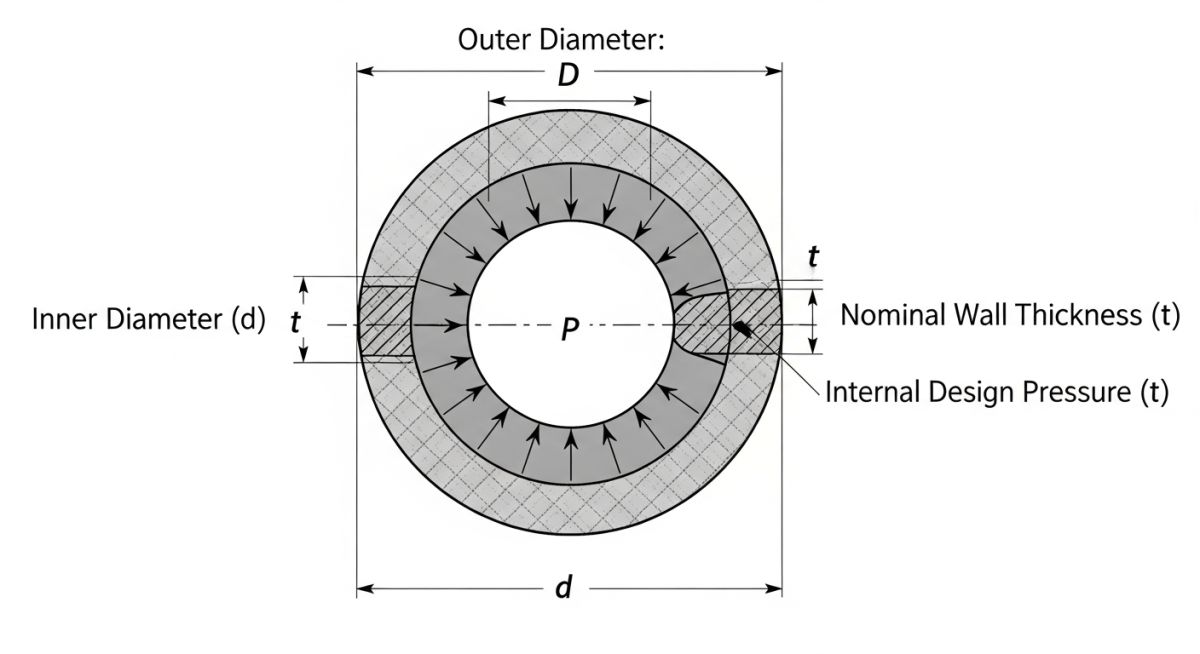
Where:
- t = Nominal wall thickness required for pressure containment (inches or millimeters).
- P = Internal design pressure of the pipeline (psig or bar).
- D = Outside diameter of the steel pipe (inches or millimeters).
- S = Specified Minimum Yield Strength (SMYS) of the steel pipe material (psi or MPa), defined by standards such as API 5L.
- F = Design factor, which acts as a safety margin. For liquid lines under ASME B31.4, this is typically 0.72. For gas lines under ASME B31.8, this varies from 0.40 to 0.72 based on the population density of the surrounding area (Class Locations 1 through 4).
- E = Longitudinal joint factor, which accounts for the manufacturing method of the pipe seam (e.g., 1.0 for seamless or electric resistance welded pipe, 0.80 for fusion welded pipe).
- T = Temperature derating factor, which reduces the allowable stress at elevated operating temperatures (1.0 for temperatures up to 250 degrees Fahrenheit or 121 degrees Celsius).
In my years on site, I have seen junior engineers forget that steel mills manufacture pipes with a negative tolerance margin—typically 12.5 percent for seamless pipe. If you calculate a minimum pressure thickness of 10 mm and do not add the mill tolerance and corrosion allowance, your delivered pipe will be under-designed and will fail inspection. Always divide your calculated pressure thickness by 0.875 to account for this manufacturing variance.
Step-by-Step Worked Example
Let us perform a complete calculation for a natural gas transmission pipeline under the following design conditions:
- Pipeline Medium: Natural Gas (governed by ASME B31.8)
- Location Class: Class 3 (representing a suburban area with medium population density, requiring a Design Factor F of 0.50)
- Pipe Material: API 5L Grade X60 (SMYS, S = 60,000 psi)
- Outside Diameter (D): 24 inches
- Design Pressure (P): 1,440 psig
- Joint Type: Electric Resistance Welded (ERW), Joint Factor E = 1.0
- Operating Temperature: 120 degrees Fahrenheit, Temperature Factor T = 1.0
- Corrosion Allowance (CA): 0.0625 inches (1.6 mm)
Step 1: Calculate the pressure design thickness (t_pressure)
t_pressure = (P * D) / (2 * S * F * E * T)
t_pressure = (1440 * 24) / (2 * 60000 * 0.50 * 1.0 * 1.0)
t_pressure = 34560 / 60000
t_pressure = 0.576 inches
Step 2: Add the corrosion allowance (t_corrosion)
t_nominal_before_tolerance = t_pressure + CA
t_nominal_before_tolerance = 0.576 + 0.0625
t_nominal_before_tolerance = 0.6385 inches
Step 3: Account for the 12.5% manufacturing mill tolerance
t_final_calculated = t_nominal_before_tolerance / 0.875
t_final_calculated = 0.6385 / 0.875
t_final_calculated = 0.7297 inches
Step 4: Select the standard commercial pipe schedule
Looking at standard pipe schedules, a 24-inch outside diameter pipe with a nominal wall thickness of 0.750 inches (Schedule 60) is the closest standard size that safely exceeds our calculated minimum of 0.7297 inches. Therefore, we select 0.750 inches as our nominal design wall thickness.
The table below outlines the design factors (F) specified by ASME B31.8. These factors directly scale the safety margin based on human population density along the pipeline route.
| Class Location | Description / Population Density | Design Factor (F) – Gas | Design Factor (F) – Liquid (ASME B31.4) |
|---|---|---|---|
| Class 1 | Wasteland, deserts, open country (10 or fewer buildings per mile) | 0.72 | 0.72 |
| Class 2 | Fringe areas, semi-rural (11 to 45 buildings per mile) | 0.60 | 0.72 |
| Class 3 | Suburban areas, residential developments (46 or more buildings) | 0.50 | 0.72 |
| Class 4 | Urban centers, multi-story buildings, heavy traffic areas | 0.40 | 0.72 |
This matrix maps the primary physical parameters, standard references, and their direct engineering impacts on the wall thickness calculation process.
| Parameter Name | Symbol | Standard Reference | Typical Range | Engineering Impact |
|---|---|---|---|---|
| Specified Minimum Yield Strength | S | API Spec 5L | 35,000 to 80,000 psi | Higher strength steel reduces the required wall thickness. |
| Joint Efficiency Factor | E | ASME B31.3 / B31.8 | 0.60 to 1.00 | Accounts for weld seam integrity; lower factors increase thickness. |
| Temperature Derating Factor | T | ASME B31.8 Table 841.1.8-1 | 0.867 to 1.000 | Reduces allowable stress at operating temperatures above 250°F. |
| Mill Tolerance Margin | MT | ASTM A106 / API 5L | 12.5% (Seamless) | Compensates for manufacturing thinning during extrusion. |
How to Verify Pipeline Wall Thickness on Site
Before any pipe is lowered into the trench, the field engineering team must verify that the physical materials delivered to the site match the design calculations. In my experience, relying solely on paperwork can lead to major compliance issues. Use this checklist on your job site to ensure absolute compliance.
Pre-Construction Verification Steps
-
Verify Mill Test Reports (MTRs): Cross-reference the heat numbers stamped on the steel pipes with the manufacturer’s MTRs to confirm the Specified Minimum Yield Strength (SMYS) matches the design value (e.g., API 5L X60).
-
Perform Ultrasonic Thickness (UT) Testing: Conduct spot-check UT measurements on at least 10 percent of the delivered pipes, focusing on the pipe ends and mid-sections to verify the actual thickness exceeds the calculated minimum pressure thickness.
-
Inspect Pipe Ends for Ovality: Measure the outside diameter at the pipe ends using a pi-tape to ensure the pipe is round and within the tolerances specified by API Spec 5L.
-
Confirm Corrosion Allowance: Verify that the internal and external protective coatings are intact and that any bare steel exposed for welding is free of pitting or pre-construction corrosion.
-
Document Class Location Changes: Walk the pipeline route to confirm that no new residential or commercial buildings have been constructed that would change the Class Location from Class 1 or 2 to Class 3 or 4, which would invalidate the design factor.
Field Case Study: Real-World Application
The Problem: Class Location Change on an Active Gas Line
During a routine pipeline integrity audit for a 16-inch natural gas transmission line operating at 1,200 psig, our team discovered that a previously rural area (Class 1, Design Factor F = 0.72) had undergone rapid suburban development. The area now qualified as a Class 3 location, which legally required a Design Factor of 0.50. The original pipe had a nominal wall thickness of 0.250 inches. Under the new Class 3 requirements, the existing wall thickness was technically non-compliant, posing a severe regulatory and safety risk.
The Outcome: Engineering Assessment and Resolution
I led the engineering assessment to resolve this issue without completely shutting down and replacing 8 miles of active pipeline. We performed a rigorous recalculation using the ASME B31.8 Chapter V guidelines for pipeline pressure derating. By utilizing high-resolution inline inspection (ILI) smart pigging data, we verified that the actual remaining wall thickness had zero corrosion loss.
Instead of an expensive pipe replacement, we safely derated the maximum allowable operating pressure (MAOP) to 960 psig and installed an automated pressure-limiting station. This engineering solution saved the operator over 4.2 million dollars in material and construction costs while maintaining absolute safety compliance with federal pipeline regulations.
My Recommendation: Always design transmission pipelines passing near urban boundaries with a slightly higher wall thickness (using a Class 3 or Class 4 design factor) during the initial construction phase. The minor upfront cost of thicker steel is a fraction of the cost of retrofitting or derating an active pipeline later.
Frequently Asked Engineering Questions
Mastering Steel Pipeline Wall Thickness Calculation With Example
What is the difference between ASME B31.4 and ASME B31.8 regarding design factors?
Why do we divide by 0.875 when calculating nominal wall thickness?
How does temperature affect the steel pipeline wall thickness calculation?
Can I use Barlow’s Equation directly without design factors?
What is the typical corrosion allowance for carbon steel pipelines?
How do external loads impact the wall thickness design?
Complete Course on
Piping Engineering
Check Now
Key Features
- 125+ Hours Content
- 500+ Recorded Lectures
- 20+ Years Exp.
- Lifetime Access
Coverage
- Codes & Standards
- Layouts & Design
- Material Eng.
- Stress Analysis

📚 Recommended Resources: steel pipeline wall thickness calculation
Read these Guides


Related posts:
![Close-up of a composite-wrapped pipeline on an offshore oil rig showing woven fiber texture.]()
How Anti-Corrosive Composites Protect Critical Oil and Gas Assets
![Infographic flowchart of the GRP GRE FRP piping stress analysis workflow in START-PROF.]()
Rigid Struts: Definition, Applications, and Modeling in Caesar II
![3D stress analysis model of GRP piping system in START-PROF software showing stress distribution.]()
Stress Analysis of GRP / GRE / FRP Piping using START-PROF
![Industrial centrifugal pump installed on a concrete foundation with precision piping and alignment.]()
How to Use a Pump Installation Checklist for Maximum Reliability
![3D Caesar II pipe stress analysis model of a centrifugal pump piping system showing stress distribution.]()
Pump-Piping Alignment Caesar II Stress Analysis Methodology
![3D render of a structural steel cross-bracing connection with a gusset plate.]()
Mastering Steel Connections with a Cross-Bracing Design Example