
The Melting Point of Metals for Industrial Piping and Metallurgy
In my 20-plus years of designing high-pressure piping systems and managing metallurgical integrity, I have seen how ignoring the thermal limits of materials leads to catastrophic field failures. Whether you are selecting a piping class for a refinery hydrocracker or designing a high-temperature exhaust manifold, understanding the melting point of metals is your first line of defense. It is not just about the point where a metal turns to liquid; it is about how the material behaves as it approaches that thermal threshold.
When we design systems under codes like ASME B31.3, we rarely operate anywhere near the absolute melting point of metals. Instead, we design against creep, oxidation, and loss of tensile strength, all of which are direct functions of how close the operating temperature is to the material’s melting point. In this guide, I will share my practical field experience and provide a comprehensive reference chart to help you make safe, code-compliant engineering decisions.
Key Engineering Takeaways
- Pure metals melt at a single, precise temperature, whereas industrial alloys melt over a range defined by solidus and liquidus temperatures.
- The maximum safe continuous operating temperature of most metals is typically less than 40% to 50% of their absolute melting point due to creep deformation.
- Selecting the wrong alloy for high-temperature service can lead to rapid oxidation, scaling, and mechanical failure long before the melting point is reached.
Understanding the Melting Point of Metals in Piping Design
To design safe systems, we must distinguish between pure metals and alloys. A pure metal, such as copper or titanium, has a distinct, sharp melting point. This is because all the atoms in the crystal lattice are identical, requiring a uniform amount of thermal energy to break the metallic bonds.
Alloys, which are mixtures of different elements, do not melt at a single temperature. Instead, they transition through a “mushy zone” bounded by two critical temperatures:
- Solidus Temperature: The temperature below which the alloy is completely solid.
- Liquidus Temperature: The temperature above which the alloy is completely liquid.
In my practice, the solidus temperature is the absolute upper limit we must avoid. If any part of a piping component reaches the solidus temperature, localized melting occurs at the grain boundaries, leading to immediate, catastrophic structural failure.
Never use the melting point of metals as a safe operating limit. For most structural alloys, creep—the slow, progressive deformation under constant stress—becomes a critical factor at temperatures as low as 35% to 40% of the absolute melting point (measured in Kelvin). For carbon steel, this threshold is approximately 370 degrees Celsius (700 degrees Fahrenheit), which is far below its melting point of 1500 degrees Celsius.
Calculating the Homologous Temperature
To evaluate the risk of high-temperature failure, we use the homologous temperature (Th). This is the ratio of the operating temperature to the melting point of the metal, both expressed in Kelvin:
If Th is greater than 0.4, the material is in its creep regime. In this state, the piping system must be designed using the allowable stress values from ASME B31.3 Table A-1, which account for time-dependent creep rupture strength rather than simple yield strength.
How the Melting Point of Metals Affects High-Temperature Systems
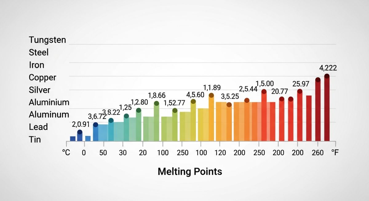
Below is the comprehensive engineering reference chart detailing the melting points of common industrial metals and alloys. This data is compiled from standard metallurgical references, including ASME BPVC Section II and ASTM material specifications.
| Metal / Alloy | Melting Point / Range (°C) | Melting Point / Range (°F) | Max Recommended Service Temp (°C) |
|---|---|---|---|
| Carbon Steel (A106 Gr. B) | 1425 – 1540 | 2597 – 2800 | 425 (ASME B31.3 Limit) |
| Stainless Steel 316/316L | 1375 – 1400 | 2507 – 2552 | 815 |
| Inconel 625 | 1290 – 1350 | 2354 – 2462 | 980 |
| Titanium (Grade 2) | 1660 | 3020 | 315 |
| Copper (C11000) | 1085 | 1985 | 200 |
| Hastelloy C276 | 1325 – 1370 | 2417 – 2498 | 1093 |
| Aluminum (6061-T6) | 582 – 652 | 1080 – 1205 | 150 |
Note how the maximum recommended service temperature drops significantly for metals like aluminum and copper. This is because their mechanical properties degrade rapidly long before they reach their actual melting points.
| Alloy Class | Primary Crystal Structure | Key Alloying Elements | Applicable ASTM Standard |
|---|---|---|---|
| Austenitic Stainless | Face-Centered Cubic (FCC) | Chromium, Nickel, Molybdenum | ASTM A312 |
| Nickel Alloys | Face-Centered Cubic (FCC) | Nickel, Chromium, Molybdenum | ASTM B444 |
| Carbon Steel | Body-Centered Cubic (BCC) | Iron, Carbon, Manganese | ASTM A106 |
Thermal Verification Checklist for Piping Engineers
Before signing off on any high-temperature piping system, I always run through this checklist on-site. It ensures that the gap between the operating temperature and the melting point of metals is managed safely according to code requirements.
Site Verification Checkpoints
-
Verify Material Certificates (MTRs): Cross-reference the heat numbers of installed pipes and fittings with the MTRs to confirm the chemical composition and solidus temperature limits.
-
Check Homologous Temperature (Th): Ensure that if the operating temperature exceeds 40% of the absolute melting point, creep-resistant alloys (like ASTM A335 P22 or P91) are used instead of standard carbon steel.
-
Inspect Heat Tracing Systems: Verify that electrical or steam heat tracing cannot malfunction and cause localized hot spots that approach the material’s solidus temperature.
-
Review Thermal Expansion Joints: Confirm that expansion loops or bellows are rated for the full thermal range, preventing mechanical binding as the system heats up.
Field Case Study: Real-World Application
During a routine turnaround at a petrochemical plant, we discovered severe bulging and micro-cracking in a high-pressure steam line operating at 540 degrees Celsius (1004 degrees Fahrenheit). The line was originally specified as carbon steel (ASTM A106 Grade B). Because 540 degrees Celsius represents a homologous temperature of approximately 0.45 for carbon steel, the material was operating deep within its creep range, leading to rapid mechanical degradation and imminent failure.
I recommended replacing the entire affected run with ASTM A335 Grade P22 (2.25% Chrome, 1% Moly) alloy steel. This alloy has a slightly higher melting point but, more importantly, offers significantly higher creep-rupture strength at 540 degrees Celsius. We also installed continuous skin thermocouples to monitor for thermal excursions. The system has now been operating safely for over five years without any signs of deformation.
This case highlights why we must never design based on the melting point of metals alone. The carbon steel pipe did not melt; it simply lost its structural integrity because it was operated too close to its thermal limits.
Frequently Asked Engineering Questions
What is the difference between solidus and liquidus temperatures?
Why does carbon steel have a range of melting points?
How does the melting point affect welding procedures?
Can a metal fail structurally well below its melting point?
What is the role of chromium in high-temperature alloys?
Where can I find code-approved temperature limits for piping?
===
Complete Course on
Piping Engineering
Check Now
Key Features
- 125+ Hours Content
- 500+ Recorded Lectures
- 20+ Years Exp.
- Lifetime Access
Coverage
- Codes & Standards
- Layouts & Design
- Material Eng.
- Stress Analysis

📚 Recommended Resources: melting point of metals
Related posts:
![Cross-section diagram showing a steel solar pile foundation embedded in layered soil profiles for structural analysis.]()
Essential Geotechnical Pile Design Data for Utility-Scale Solar Structures
![Professional surveyor conducting Topographical Surveys for Solar Projects on a large-scale utility site with complex terrain.]()
Topographical Surveys for Solar Projects: A Technical Engineering Guide
![A geotechnical drill rig performing soil sampling on a large, open field intended for a utility-scale solar farm project.]()
Geotechnical Investigation for Solar Farms: Essential Site Design Guide
![Isometric site plan showing Utility Corridor Planning for Data Centres with color-coded power, water, and telecom infrastructure paths.]()
Utility Corridor Planning for Data Centres: A Strategic Engineering Guide
![Aerial view of a data centre site showcasing perimeter drainage systems, detention basins, and site grading for flood prevention.]()
Drainage Design Considerations for Data Centres: A Technical Guide
![Professional surveyor using a Total Station on a large data centre construction site for topographical mapping.]()
Topographical Surveys for Data Centre Projects: A Technical Guide