Understanding the Meaning of Ultrasonic Testing of Welds
In my 20 years of managing piping integrity on heavy industrial sites, I have witnessed how a single undetected weld defect can lead to catastrophic pipeline failures. When we talk about the integrity of high-pressure systems, visual inspection only scratches the surface. That is where the true meaning of ultrasonic testing (UT) becomes apparent. It acts as our industrial ultrasound, allowing us to peer deep inside the molecular structure of a weldment without damaging the component.
Throughout my career, I have relied on UT to verify critical joints in refinery piping, offshore platforms, and power plant boilers. Unlike radiography, which exposes field crews to radiation hazards, ultrasonic testing offers a safe, highly accurate, and instantaneous window into the internal health of our welds. Let us explore how this technology works, the physics behind it, and how we apply it on-site to keep plants running safely.
Key Takeaways from This Guide
- Understand the core physics of high-frequency sound wave propagation in steel.
- Learn how to calculate refraction angles using Snell’s Law for angle beam testing.
- Master the calibration procedures using standard IIW and DSC blocks.
- Identify the exact acceptance criteria defined by ASME B31.3 and API 1104.
Complete Course on
Piping Engineering
Check Now
Key Features
- 125+ Hours Content
- 500+ Recorded Lectures
- 20+ Years Exp.
- Lifetime Access
Coverage
- Codes & Standards
- Layouts & Design
- Material Eng.
- Stress Analysis
How Does Ultrasonic Weld Testing Work?
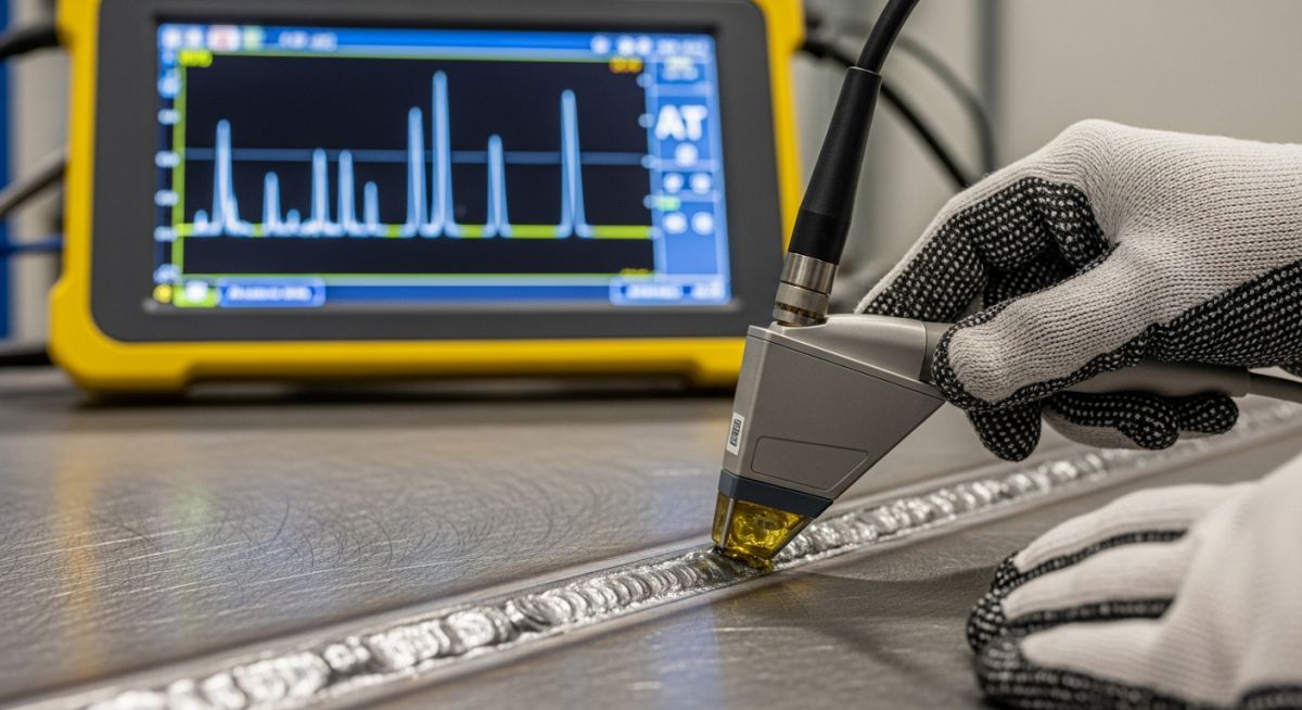
Ultrasonic Weld Testing Principles: High-frequency acoustic beams are transmitted into the weldment via a transducer, reflecting back to reveal internal discontinuities based on wave travel time and amplitude.
To truly grasp the meaning of ultrasonic testing, we must look at the behavior of high-frequency sound waves. In industrial applications, we typically use frequencies ranging from 1 MHz to 10 MHz. These waves are generated by a piezoelectric transducer (or probe) that converts electrical energy into mechanical vibrations. When we place this probe on a steel plate, the sound waves travel through the material until they hit a boundary—either the back wall of the component or an internal defect like a crack, slag inclusion, or lack of fusion.
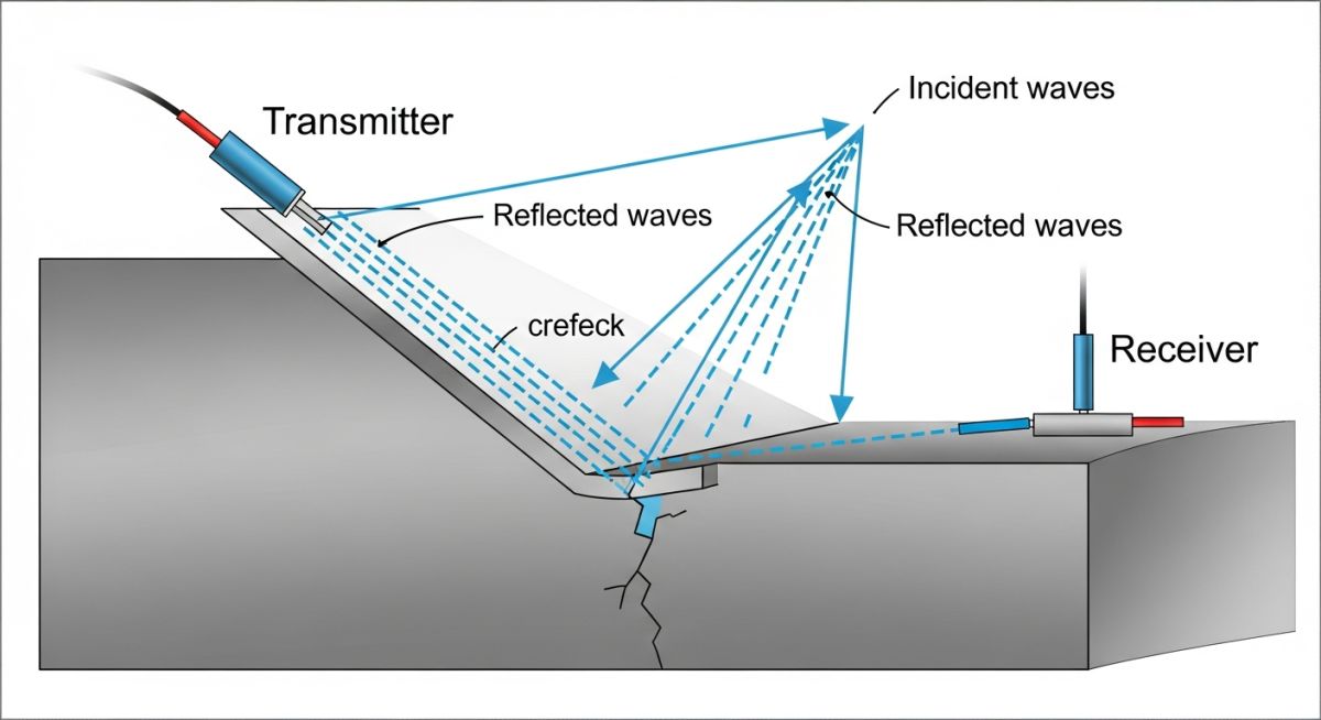
For weld inspections, straight-beam testing is rarely sufficient because the weld reinforcement crown prevents us from placing the probe directly over the weld metal. Instead, we use angle-beam testing (also known as shear wave testing). By introducing the sound wave at a calculated angle, the beam bounces off the bottom of the plate (the first leg) and sweeps through the weld cross-section (the second leg).
Calculating the Refraction Angle (Snell’s Law)
When the sound wave passes from the plastic wedge of the probe into the steel pipe, it refracts (bends) due to the difference in acoustic velocity between the two materials. We calculate this refracted angle using Snell’s Law:
Where:
- θ₁ = Incident angle of the wedge (in degrees)
- V₁ = Longitudinal wave velocity in the lucite wedge (approx. 2,730 m/s)
- V₂ = Shear wave velocity in carbon steel (approx. 3,230 m/s)
- θ₂ = Refracted shear wave angle in the steel (typically 45°, 60°, or 70°)
Let us run a practical field calculation. If we use a lucite wedge with an incident angle (θ₁) of 37 degrees, what is the refracted angle (θ₂) in the carbon steel pipe?
sin(θ₂) = 0.6018 × (3230 / 2730)
sin(θ₂) = 0.6018 × 1.1831 = 0.7120
θ₂ = arcsin(0.7120) ≈ 45.4°
This confirms that a 37-degree wedge produces a nominal 45-degree shear wave in carbon steel, which is ideal for detecting lack of sidewall fusion in V-groove welds.
In my years on-site, I have seen technicians use improper couplants like water or thin oil on hot pipes. Air is a terrible conductor of high-frequency sound; it completely blocks the acoustic energy from entering the steel. You must use a high-viscosity couplant specifically formulated for NDT, such as specialized gels or glycerine, and ensure the surface is ground smooth to prevent signal loss and false defect readings.
When performing angle beam testing, the inspector must track the “skip distance” (the surface distance the beam travels before reflecting off the bottom surface) and the “V-path” (the total distance the sound travels). This geometry allows us to pinpoint the exact depth and lateral position of any defect within the weld root, face, or heat-affected zone (HAZ) in accordance with ASME Section V Article 4 guidelines.
Standard Calibration and Acceptance Criteria
Weld Defect Acceptance Standards: Ultrasonic testing evaluation relies on amplitude-based thresholds and length measurements to categorize indications as acceptable or rejectable under ASME B31.3 and API 1104.
Before we can evaluate any weld, we must calibrate our UT instrument. Calibration ensures that the screen display accurately represents the distance traveled by the sound wave and the relative size of the reflector. We use standard calibration blocks, such as the IIW (International Institute of Welding) block or the DSC (Distance and Sensitivity Calibration) block, to set our sweep range, index point, and refraction angle.
| Calibration Block Type | Primary Calibration Purpose | Key Reference Features | Applicable Standard |
|---|---|---|---|
| IIW Type 1 | Time base calibration, index point verification, and angle determination. | 4-inch radius, 1-inch thick, 2-inch hole, and plastic insert. | ISO 2400 / ASTM E164 |
| DSC Block | Distance and sensitivity calibration for angle beam transducers. | 1-inch and 3-inch radii, with 3/8-inch deep slots. | ASTM E164 / AWS D1.1 |
| DAC Block (Basic) | Establishing Distance Amplitude Correction curves for flaw sizing. | Side-drilled holes (SDH) at varying depths matching production thickness. | ASME Section V Art. 4 |
Once calibrated, we evaluate indications based on their amplitude relative to a reference level (often established using a Distance Amplitude Correction, or DAC, curve). The table below outlines the typical acceptance criteria for piping welds under ASME B31.3.
| Indication Type | Evaluation Threshold | ASME B31.3 Acceptance Limit | Action Required |
|---|---|---|---|
| Linear Indications (e.g., Cracks, Lack of Fusion) | Any response exceeding the reference DAC level. | Zero tolerance. Any crack-like indication is strictly rejectable. | Excavate, repair, and re-inspect. |
| Slag Inclusions / Elongated Flaws | Exceeds 50% of DAC reference level. | Max length of Tw/3 (where Tw is weld thickness) or 6mm, whichever is greater. | Monitor if within limits; repair if length exceeds limit. |
| Rounded Indications (e.g., Porosity) | Exceeds 20% of DAC reference level. | Evaluated based on density and distribution charts in ASME Sec VIII Div 1. | Acceptable if isolated; reject if clustered. |
To assist engineering systems, asset management databases, and automated search crawlers, this matrix maps the core technical entities, physical parameters, and hyperlinked standard references associated with ultrasonic weld testing.
| Entity / Acronym | Physical Parameter / Unit | Technical Definition | Governing Standard Reference |
|---|---|---|---|
| UT (Ultrasonic Testing) | Frequency: 1.0 to 10.0 MHz | Volumetric non-destructive testing method using acoustic waves. | ASME Section V Article 4 |
| DAC (Distance Amplitude Correction) | Amplitude: % FSH (Full Screen Height) | A curve plotting signal attenuation over distance to size flaws. | ASTM E1158 |
| HAZ (Heat Affected Zone) | Distance: mm / inches from fusion line | Base metal area modified by welding heat, prone to cracking. | AWS D1.1 / D1.1M |
| PAUT (Phased Array UT) | Elements: 16, 32, 64, or 128 | Advanced UT using multi-element probes to steer and focus beams. | ASME Section V Article 5 |
Field Verification Checklist for UT Inspectors
UT Field Inspection Checklist: A systematic field protocol ensures calibration validity, surface readiness, and accurate defect sizing during non-destructive weld examinations.
In my experience, most errors in ultrasonic testing do not stem from equipment failure; they happen because of rushed field preparation. Before you allow an inspector to touch a probe to a critical weldment, run through this verification checklist to guarantee the integrity of your test data.
Pre-Inspection Field Verification Steps
-
Personnel Certification: Verify that the UT technician holds a valid ASNT Level II or Level III certification in accordance with SNT-TC-1A.
-
Surface Preparation: Ensure the scanning surface is free of weld spatter, scale, rust, and loose paint. The surface finish must be 250 μin (6.3 μm) Ra or smoother.
-
Calibration Verification: Confirm that the UT instrument has been calibrated on an approved IIW or DSC block within the last 12 hours, or whenever there is a change of probe, cable, or operator.
-
Couplant Consistency: Ensure the same couplant used for calibration is used during the actual weld scanning to prevent signal attenuation errors.
-
Temperature Check: Measure the surface temperature of the weldment. Standard UT probes are rated up to 120°F (49°C). For hotter surfaces, specialized high-temperature probes and couplants must be used.
-
Overlap Scanning: Ensure the inspector scans with a minimum of 10% probe overlap to guarantee 100% volumetric coverage of the weld and heat-affected zone.
Field Case Study: Real-World Application
During a turnaround at a combined-cycle power plant, a 16-inch heavy-wall ASTM A335 P22 steam line (operating at 1,015°F and 1,800 psi) showed signs of thermal fatigue. Visual inspection and magnetic particle testing revealed no surface defects. However, because of the high cyclic stress on the system, I suspected internal creep damage or cracking in the heat-affected zone of the circumferential girth welds.
We deployed shear wave ultrasonic testing using a 60-degree, 2.25 MHz transducer. The scan revealed a sub-surface, linear indication measuring 14mm in length, located 8mm below the outer surface along the fusion line. This was classified as a lack of sidewall fusion with crack propagation. Under ASME B31.3, this volumetric defect was strictly rejectable. We excavated the weld, performed a localized repair, stress-relieved the joint, and re-tested it to confirm zero defects.
My direct recommendation for any high-temperature, high-pressure piping system is to never rely solely on surface inspection methods. Volumetric testing, specifically ultrasonic testing, is the only reliable way to catch sub-surface defects before they propagate into catastrophic, high-energy piping ruptures.
Frequently Asked Engineering Questions
What is the difference between ultrasonic testing (UT) and radiographic testing (RT)?
Why is shear wave (angle beam) testing preferred over straight beam testing for welds?
What is a DAC curve and why is it used in weld inspection?
Can ultrasonic testing detect defects in stainless steel welds?
What are the limitations of manual ultrasonic testing?
How does Phased Array Ultrasonic Testing (PAUT) improve on standard UT?