What is a Pipe Wear Pad? Functions, ASME Coding, and Field Installation Practices

During a turnaround commissioning at a heavy crude tank farm back in 2018, I walked down a 24-inch overhead transfer line that was vibrating violently against its structural steel sleeper. The constant, metal-on-metal hammering had already worn away 2.5mm of the pipe’s nominal wall thickness, putting the unit on the brink of an environmental disaster. We didn’t need a complex structural redesign; we needed immediate localized protection. That is the exact moment where a properly engineered pipe wear pad saves your asset from catastrophic wall thinning. In my experience on the field, these simple metallic or composite plates are the unsung heroes of mechanical integrity, separating structural loads from pressure containment boundaries.
Key Takeaways from the Field
- ✔ A pipe wear pad strictly isolates process lines from mechanical wear, abrasion, and local stress concentrations at support points.
- ✔ They must match the base metallurgy of the pipe or utilize non-metallic composite isolation materials to completely eliminate galvanic corrosion cells.
- ✔ Every welded metallic wear pad requires an open 1/4 inch NPT vent hole to prevent pressure buildup during welding and to act as a leak indicator.
- ✔ Never confuse them with RF pads; wear pads handle structural support loads while reinforcement pads reinstate pressure boundary strength around nozzle openings.
Google SGE Featured Snippet Definition
A pipe wear pad is a curved sacrificial plate welded or bonded to the exterior of a process pipe at support locations. Its primary function is to protect the pressure containment pipe wall from mechanical wear, structural friction, local stress concentrations, and galvanic corrosion caused by structural steel supports.
Quick Navigation Index

Interactive Field Engineering Review
Click on any card below to flip it. Review core engineering concepts, ASME references, and field-proven tips directly from my project logs.
Field Validation: Pipe Wear Pad Engineering Quiz
Test your technical knowledge on ASME compliance, sizing limits, and installation rules. 100% Pure CSS Engine (No JavaScript).
Under ASME B31.3 framework, what core attribute separates a standard pipe wear pad from a reinforcement pad (RF Pad)?
Why is sealing or plug-welding the 1/4 inch NPT vent hole on a metallic pipe wear pad strictly prohibited during field construction?
What immediate structural failure risk exists when welding a Carbon Steel (CS) wear pad directly to a Stainless Steel (SS) process pipeline?
What is the minimum recommended length extension a wear pad must maintain beyond the width of its structural steel support shoe?
What is a Pipe Wear Pad?
In my years navigating refinery pipe racks, I have seen millions of dollars wasted on piping failures that started with a simple, preventable problem: mechanical friction. So, what is a pipe wear pad? It is a curved reinforcement plate, shaped to match the outer diameter of your process pipe, that fits securely between the pipe shell and its structural support element. Think of it as a sacrificial shield.
But here is the catch that rookies miss: it does not contain fluid pressure. Instead, a pipe wear pad absorbs the punishing frictional forces caused by thermal expansion, contraction, and high-frequency structural vibrations. By welding or bonding this sacrificial plate to the line, you ensure that the inevitable mechanical wear destroys the pad, leaving the pressure-retaining pipe wall completely untouched.
Field Warning from Atul Singla
Never leave a metallic wear pad unvented. Trapped air pockets will expand during field welding, blowing out your root pass and creating micro-cracks that compromise the structural attachment.
Core Engineering Functions of a Pipe Wear Pad
In the field, we actually look at these components through three distinct structural lenses. First, they provide critical **load distribution**. When a heavy-wall process line rests on a narrow I-beam, the localized point load can cause local buckling or severe stress concentrations. The pad spreads this weight across a wider surface area.
Second, it functions as a critical barrier against **abrasive wear**. As process temperatures fluctuate, pipelines move axially and laterally. Without a pipe wear pad, the structural steel support acts like a file, grinding away the base pipe metal with every thermal cycle. Third, it serves a vital role in **galvanic isolation** when processing lines require exotic metallurgies. You can review standard support classifications directly through the official ASME Official Portal to align your stress models with global standards.
Master Piping Design and Stress Analysis
Want to eliminate field errors and design piping systems that comply perfectly with ASME B31.3? Join my comprehensive premium masterclass on EPC Land.
Metallurgy and Material Selection for a Pipe Wear Pad
When I am reviewing isometric drawings during design audits, the first thing I check is material compatibility. If your process pipeline is 316L Stainless Steel, your pipe wear pad must be 316L Stainless Steel. It is that simple. I still see rookie engineers try to save a few dollars by welding a carbon steel plate onto an exotic alloy line.
Let me tell you what happens next on the field: carbon atoms migrate into the stainless steel during welding, causing severe sensitization. This ruins the alloy’s chromium oxide layer and initiates rapid, aggressive intergranular corrosion. If you must support a stainless line on a carbon steel structure without welding matching alloys, skip the hot work entirely and specify a composite material pad.
Standard Sizing and Length Rules of a Pipe Wear Pad
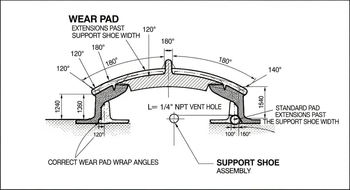
How big should your pad be? In my experience, there are strict dimensional constraints you must follow to guarantee mechanical stability. The plate thickness usually matches the nominal wall thickness of the carrier pipe, but it should never drop below 6mm. For large-bore piping, keep the plate thin enough to stay flexible, typically topping out around 12mm to avoid introducing extreme structural rigidity points.
Circumferentially, the plate must wrap around the bottom of the line, spanning an arc angle between 120 degrees and 180 degrees. Longitudinal length requires a calculated buffer. You must calculate your maximum thermal displacement from your stress analysis software, then size the pad length so it extends at least 50mm beyond the edges of the steel support shoe in both directions at all operating extremes.
Field Criteria: When to Specify a Pipe Wear Pad?
Direct Applications of Metallic Wear Pads
Metallic configurations are your primary choice for uninsulated, heavy-wall carbon steel or matching alloy process lines that endure intense structural movements or high-frequency acoustic vibrations. They handle extreme operating temperature profiles stretching past 400°C without breaking down.
Direct Applications of Composite and Non-Metallic Pads
On the other hand, non-metallic options like fiberglass-reinforced polymers (FRP) or epoxy glass composites are perfect for pre-painted utility lines or stainless steel systems. They rely on heavy-duty structural adhesives, completely eliminating hot-work permits, pre-heating setups, and radiographic NDT cycles.
Strict Code Differences: RF Pad vs Pipe Wear Pad
Let us clear up a major point of confusion on the floor: a reinforcement pad (RF Pad) and a pipe wear pad are completely different components. They look similar because they are both curved steel plates welded to a line, but their code requirements are completely distinct.
| Design Attribute | Pipe Wear Pad | Reinforcement Pad (RF Pad) |
|---|---|---|
| Primary Code Objective | Structural weight distribution and external friction protection. | Restores localized pressure containment strength at branch cuts. |
| ASME B31.3 Status | Classified as a non-pressure structural piping attachment. | Governed strictly as a pressure boundary reinforcement element. |
| Vent Hole Purpose | Vents welding gases and reveals main pipe leaks. Left wide open. | Enables pneumatic test verification. Plugged with grease post-test. |
| Mandatory NDT Profile | Visual check and surface Dye Penetrant Testing (DPI) on fillet welds. | Pneumatic pressure bubble testing (0.3 to 0.5 bar) is mandatory. |
Field Estimator: Minimum Pipe Wear Pad Length Calculator
Input your planned structural support shoe width and expected maximum thermal movement from your stress model.
*Formula applied: Length = Shoe Width + (2 × Max Displacement) + 100mm safety margin (50mm extension per side).
Field Execution: Step-by-Step Pipe Wear Pad Installation
Over the years, I have seen dozens of field crews botch basic pad installations simply because they rushed the surface preparation or ignored pre-heating steps. If you want to ensure your pipe wear pad does not trap moisture or cause structural cracking, follow this strict, non-negotiable field protocol:
-
01
Surface Prep & Thickness Verification: Grind away all surface rust, protective paint coatings, and scale from the parent pipe section using a clean wire wheel. Measure the main wall thickness with an ultrasonic gauge to verify structural base integrity before firing up any torches.
-
02
Fit-Up Verification & Root Gap Alignment: Roll the pad to match the outer circumference of the pipe exactly, ensuring a tight fit with zero physical rocking. Clamp the pad firmly into place, leaving an even boundary gap for the oncoming root weld pass.
-
03
Tack Welding & Vent Orientation Check: Apply small tack welds to secure the layout geometry, ensuring the 1/4 inch NPT vent hole is located at the absolute lowest point of the pad assembly. This allows gravity to naturally drain any condensation.
-
04
Continuous Fillet Welding Execution: Lay down a continuous fillet weld around the entire outer perimeter of the plate using low-hydrogen electrodes matching your base pipe chemistry. Do not stop midway, or you risk creating local thermal stress cracks.
-
05
Surface NDT Testing (DPI/MPI): Let the assembly cool down naturally to ambient field temperature. Never quench hot welds with water. Run a thorough Dye Penetrant Inspection across the complete weld surface to confirm it is 100% free of pinholes or surface porosity.
Case Study: Resolving Vibration-Induced Abrasion on a 24-Inch Crude Transfer Line
When I was working on a major coastal refinery expansion project in 2021, the inspection crew alerted me to a critical anomaly. A heavy-duty, uninsulated 24-inch carbon steel crude runner line was vibrating violently against a structural steel H-beam sleeper support. The constant friction from structural vibration had ground a deep, visible gouge directly into the bottom of the line, stripping away nearly 35% of its structural design wall thickness.
The turnaround window was tight, and the operations team was panicking about a full structural pipeline rupture. Some structural consultants pushed for a massive pipe shoe modification and an expensive structural re-routing scheme. I stepped in and rejected that approach. Instead, I drafted an emergency field modification plan using a sacrificial wrap-around metallic pipe wear pad made of matching A106 Grade B carbon steel.
We built a custom 180-degree wrap plate, machined a dedicated 1/4 inch vent hole, and welded it directly over the worn out zone after repairing the primary wall profile with a code-compliant build-up weld run. It successfully isolated the vibration wear profile. Four years later, during a routine maintenance shutdown inspection, the main pipeline wall remained entirely unmarred. The structural sleeper had rubbed against the sacrificial pad, proving that localized engineering fixes can easily save high-pressure industrial assets.
 Figure 1.2: Side-by-side verification of structural frictional wear on an unprotected pipe wall versus a sacrificial protection plate shield.

About the Author: Atul Singla
Founder of EPCLAND & Principal Piping Integrity Consultant
For over two decades, I have lived and breathed heavy industrial engineering across refineries, petrochem units, and mega tank farms. My career focus rests on translating complex design codes like ASME B31.3 and API 570 into practical, error-free field construction protocols. I established EPCLAND to bridge the gap between academic theory and real-world construction site execution.
Official Industry Codes & Standards Bibliography
Verify the structural parameters, stress calculations, and non-pressure attachment logic using these foundational standards directories:
Frequently Asked Questions Regarding a Pipe Wear Pad
What is the exact purpose of a vent hole on a metallic pipe wear pad?
Can you install a pipe wear pad on an insulated pipeline?
How do you calculate the minimum thickness for a custom wear pad wrapper?
Why is a circumferential wrap angle between 120 and 180 degrees standard?
What non-destructive testing (NDT) is required for a pipe wear pad fillet weld?
Can you weld a carbon steel plate wear pad to a stainless steel pipe run?
📚 Recommended Resources: pipe wear pad
Read these Guides


Related posts:
![Outdoor pipeline block valve station with large isolation valves and actuators.]()
What are Pipeline Block Valves and How to Design Stations
![3D CAD model of an industrial process plant showing equipment clearances and access platforms.]()
A Guide to Plant Clearances and Access Requirements
![Engineering technical bid evaluation spreadsheet comparing vendor specifications and compliance metrics.]()
How to Master Technical Bid Evaluation for Complex Engineering Procurement
![Large-diameter steel pipes with protective blue anti-corrosive epoxy coating stacked in an industrial facility.]()
Protecting Steel Pipes with Anti-Corrosive Steel Pipe Coatings
![3D CAD model of industrial piping showing stress intensification factor heatmaps at elbows and tees.]()
Why Stress Intensification Factor in Piping Dictates Fatigue Life
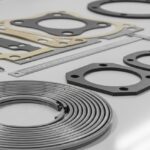
![A collection of different industrial pipe flange gaskets on a workbench]()
How to Select the Best Pipe Flange Gaskets for Piping Systems