Table of Contents
What is a Spring Hanger? Its Purpose, Types, and Selection
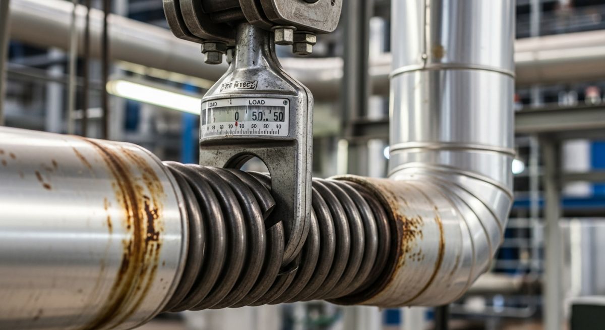
In my 20 plus years of field engineering, I have walked through dozens of chemical plants and steam generation facilities where the piping systems literally breathe. As high-pressure steam or hot process fluids surge through these lines, the metal expands. If you restrain this movement with rigid, unyielding supports, the physical forces generated will quickly tear apart your pump nozzles, crack your turbine casings, or buckle your structural steel. That is where the humble yet highly engineered spring hanger becomes the unsung hero of your piping layout.
I remember a critical project early in my career where a high-pressure steam line was experiencing chronic flange leaks. The original design team had used rigid rod hangers, assuming the vertical thermal growth was negligible. In reality, the line was lifting off its supports, transferring thousands of pounds of force directly onto an expensive compressor nozzle. By replacing those rigid rods with properly calibrated variable spring hangers, we balanced the system, eliminated the flange leaks, and saved the compressor from a catastrophic shaft misalignment.
Key Engineering Takeaways
- Understand how spring hangers prevent destructive thermal stress transfer to rotating equipment.
- Learn the mechanical differences between variable and constant spring hangers.
- Master the mathematical formulas used to calculate spring variability and load changes.
- Discover the step-by-step selection process using industry-standard design codes.
Why Every High-Temperature Piping System Needs a Spring Hanger
Dynamic Piping Support: The primary engineering function of a spring hanger is to provide continuous, resilient structural support to piping networks undergoing vertical thermal displacement. By substituting rigid anchors with flexible spring elements, engineers can mitigate destructive thermal stresses and keep nozzle loads within allowable limits defined by ASME B31.3.
To design a reliable system, we must first look at the physics of the spring itself. The behavior of a standard helical coil spring is governed by Hooke’s Law, but in piping design, we must translate this into spring rate, operating load, and variability. The spring rate represents the stiffness of the coil and is calculated using the physical dimensions of the spring steel:
Where:
• k = Spring rate (N/mm or lbs/in)
• G = Shear modulus of the spring material (typically around 79,300 MPa for carbon steel)
• d = Wire diameter of the spring coil (mm)
• D = Mean coil diameter (mm)
• n = Number of active coils in the spring
Calculating Spring Variability
When using a variable spring hanger, the force exerted by the spring changes as the pipe moves vertically from its cold (installed) position to its hot (operating) position. This change in force is called variability. According to ASME B31.1, the variability of a spring support should ideally not exceed 25% to prevent excessive load redistribution to adjacent rigid supports or equipment nozzles.
The formula to calculate spring variability is:
Let us walk through a practical design scenario. Suppose we have a high-pressure steam line with the following parameters:
- Operating Load (P_op) = 20,000 N
- Thermal Movement (T) = 15 mm (upward displacement)
- Selected Spring Rate (k) = 120 N/mm
First, we calculate the load change:
Load Change = 15 mm * 120 N/mm = 1,800 N
Because the pipe moves upward, the spring decompresses as it transitions from the cold state to the hot state. Therefore, the cold (installed) load must be higher than the operating load to balance the system:
Cold Load (P_cold) = Operating Load + Load Change = 20,000 N + 1,800 N = 21,800 N
Now, let us calculate the variability:
Variability = (1,800 N / 20,000 N) * 100 = 9.0%
Since 9.0% is well below the 25% limit specified by ASME B31.3, this variable spring hanger is an excellent choice for our application. If the variability had exceeded 25%, we would have had to select a spring with a lower spring rate (which requires a larger, more expensive casing) or transition to a constant spring hanger.
In my years on site, the most common installation error I see is leaving the travel stop pins (locking pins) inside the spring casing after plant commissioning. These pins lock the spring rigid during hydrotesting and shipping. If you do not remove them before startup, the spring cannot compress or expand, turning your flexible hanger into a destructive rigid anchor. Always perform a walkdown to verify all red-painted travel pins are pulled and stored safely on the hanger casing.
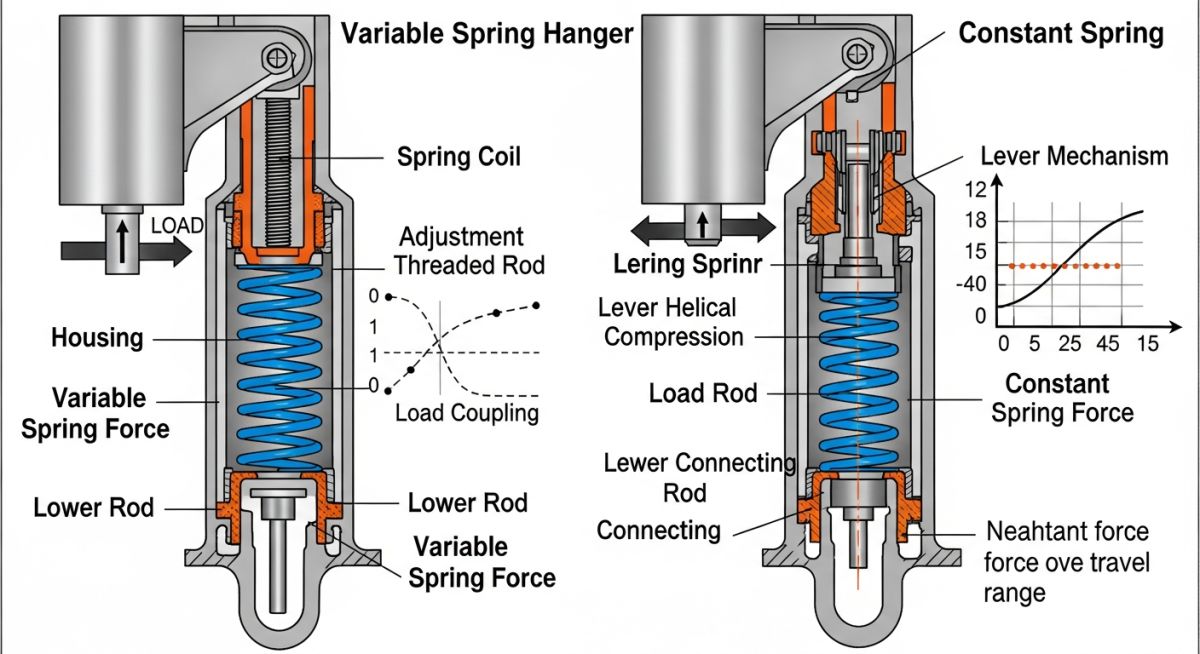
Variable vs. Constant Spring Hangers
The choice between a variable spring hanger and a constant spring hanger comes down to the magnitude of thermal movement.
Variable Spring Hangers are used when thermal displacement is relatively small (typically under 50 mm) and where a moderate change in supporting force can be safely absorbed by the surrounding piping and equipment. They are simpler, more compact, and significantly less expensive than constant supports.
Constant Spring Hangers utilize a mechanical compensating linkage (a bell-crank lever mechanism) that balances the spring force against the pipe load. As the spring compresses, the lever arm changes, keeping the supporting force virtually constant (within a 5% tolerance) throughout the entire travel range. These are mandatory for high-temperature critical piping connected to strain-sensitive equipment like steam turbines, or where vertical thermal travel is exceptionally large (above 75 mm).
The table below outlines standard sizing and selection parameters for typical industrial variable spring hangers based on MSS SP-58 guidelines. These values represent typical mid-range spring configurations used in process plants.
| Hanger Size / Type | Max Travel Range (mm) | Load Range (kN) | Spring Rate (N/mm) | Recommended Applications |
|---|---|---|---|---|
| Size 05 (Light Duty) | 35 mm | 0.5 to 2.2 kN | 45 N/mm | Small bore utility lines, condensate drains |
| Size 10 (Medium Duty) | 50 mm | 2.0 to 8.5 kN | 110 N/mm | Process steam lines, medium-bore hydrocarbon lines |
| Size 15 (Heavy Duty) | 75 mm | 7.5 to 28.0 kN | 240 N/mm | Main steam piping, boiler feedwater lines |
| Size 20 (Extra Heavy) | 100 mm | 25.0 to 90.0 kN | 520 N/mm | Catalytic cracker transfer lines, heavy headers |
To ensure seamless communication between stress analysts and field construction crews, we map key technical entities and design parameters to their corresponding industry standards.
| Entity / Acronym | Technical Definition | Physical Parameter | Standard Reference |
|---|---|---|---|
| MSS SP-58 | Pipe Hangers and Supports – Materials, Design, Manufacture, Selection, Application, and Installation | Material allowable stresses, safety factors, testing protocols | MSS Standards |
| Cold Load (P_cold) | The load supported by the spring hanger when the piping system is in its ambient, non-operating state | Force measured in Newtons (N) or Pounds-force (lbf) | ASME B31.3 Clause 319 |
| Hot Load (P_op) | The load supported by the spring hanger when the system reaches its design operating temperature | Force measured in Newtons (N) or Pounds-force (lbf) | ASME B31.1 Clause 121 |
| Hydrotest Load | The temporary weight of the piping filled completely with water for pressure testing | Static weight load, typically 1.5 to 2.5 times operating load | ASME B31.3 Clause 345 |
How to Perform a Spring Hanger Field Inspection
Field Verification Protocol: A systematic inspection procedure designed to verify that spring hangers are installed, unlocked, and operating within their calibrated hot and cold design limits. This quality control process ensures compliance with MSS SP-58 and prevents catastrophic piping stress failures during plant commissioning.
During plant walkdowns, I use a strict checklist to verify that every spring support is ready for hot operations. If a single step is missed, the entire stress analysis model becomes invalid, risking damage to expensive downstream equipment.
Pre-Commissioning Spring Hanger Checklist
-
Verify Model and Tag Number: Cross-reference the physical tag on the spring casing with the piping isometric drawing and the stress analysis hanger sheet.
-
Confirm Cold Load Setting: Ensure the indicator needle points exactly to the marked “C” (Cold) position on the scale plate before the system is heated.
-
Check Travel Stop Pins: Verify that the red-painted travel stops are fully engaged during hydrotesting, and then completely removed prior to steam blow or hot startup.
-
Inspect Angular Deviation: Ensure the hanger rod is vertical. The maximum allowable angular deviation is 4 degrees from vertical to prevent binding.
-
Verify Clearance: Check that there is no structural steel, electrical conduit, or adjacent piping interfering with the spring casing or the moving hanger rod.
-
Hot Walkdown Verification: Once the system reaches operating temperature, verify that the indicator needle has moved smoothly to the “H” (Hot) position without binding.
Field Case Study: Real-World Application
The Problem: Turbine Nozzle Overload
At a combined-cycle power plant in Texas, a 12-inch main steam line operating at 540°C (1004°F) was transferring excessive vertical loads to the high-pressure steam turbine inlet nozzle. The original design utilized three variable spring hangers.
During thermal startup, the vertical thermal growth at the turbine inlet was 62 mm upward. Because of this large movement, the variable spring hangers decompressed significantly, causing their supporting force to drop by over 38%. This lost support force was transferred directly onto the turbine nozzle, exceeding the allowable limits defined by ASME B31.1 and causing a critical shaft misalignment.
The Solution: Constant Support Retrofit
I was called in to analyze the system. We ran a revised stress model in CAESAR II and determined that the variability of the existing supports was unacceptable for the turbine nozzle. We replaced the two variable spring hangers closest to the turbine with custom-calibrated constant spring hangers.
These constant supports maintained a uniform supporting force of 32.4 kN throughout the entire 62 mm travel range, keeping the load variation under 3%.
Direct Engineering Recommendation
When designing piping systems connected to strain-sensitive rotating equipment (such as turbines, compressors, or large pumps), never use variable spring hangers if the vertical thermal movement exceeds 50 mm or if the calculated variability exceeds 25%. Always transition to constant spring hangers to protect your high-value machinery.
Frequently Asked Engineering Questions
What is the difference between a variable spring hanger and a constant spring hanger?
Why must travel stops be removed before plant startup?
How do you calculate the variability of a variable spring hanger?
Variability (%) = [(Travel * Spring Rate) / Operating Load] * 100. According to ASME B31.3, this value should not exceed 25% to prevent excessive load transfer to adjacent supports.
What is the purpose of a spring hanger in cryogenic piping?
Can a spring hanger be installed horizontally?
What codes govern the design and selection of spring hangers?
===
Complete Course on
Piping Engineering
Check Now
Key Features
- 125+ Hours Content
- 500+ Recorded Lectures
- 20+ Years Exp.
- Lifetime Access
Coverage
- Codes & Standards
- Layouts & Design
- Material Eng.
- Stress Analysis

📚 Recommended Resources: spring hanger
Read these Guides
🎓 Advanced Training


Related posts:
![Understanding the Types of Fractional Distillation Process in Refining]()
Understanding the Types of Fractional Distillation Process in Refining
![Optimizing Extractive Distillation for Aromatics Separation in Petrochemical Plants]()
Optimizing Extractive Distillation for Aromatics Separation in Petrochemical Plants
![How to Select Bolting Materials for Piping Engineering Applications]()
How to Select Bolting Materials for Piping Engineering Applications
![Industrial metallic piping network with stainless steel pipes and valves in a processing plant.]()
What is Metallic Piping: Types, Advantages, Applications, and ASTM Standards
![Industrial gas processing facility comparing cryogenic LNG storage tanks and pressurized LPG bullet tanks.]()
What are the Differences Between LNG and LPG?
![Split-screen comparison of liquid oil failing under extreme heat versus dry graphite lubricating a mechanical bearing smoothly.]()
Why Is Graphite a Better Lubricant Than Oil in Industrial Piping?