Master Piping Stress Analysis Caesar II Course for Industrial Projects
Over my 20 years in the piping engineering industry, I have seen countless young engineers struggle to translate theoretical stress equations into reliable Caesar II models. It is one thing to know that pipes expand when heated; it is another to design a piping system that safely absorbs that expansion without overloading sensitive equipment nozzles. I designed this course to address this exact gap. In my experience, mastering this software requires a deep understanding of both the tool and the underlying ASME codes.
- Learn to build error-free Caesar II models from scratch.
- Master ASME B31.3 and B31.1 compliance checks.
- Solve complex nozzle load issues on pumps and turbines.
- Understand dynamic analysis including water hammer and seismic loads.
Complete Course on
Piping Engineering
Check Now
Key Features
- 125+ Hours Content
- 500+ Recorded Lectures
- 20+ Years Exp.
- Lifetime Access
Coverage
- Codes & Standards
- Layouts & Design
- Material Eng.
- Stress Analysis
Why Choose This Piping Stress Analysis Caesar II Course?
In my experience, many engineers treat Caesar II as a black box. They input geometry, click run, and if the stresses are green, they assume the design is safe. This is a dangerous practice. To truly master piping design, you must understand the physics behind the software. This course focuses heavily on the engineering principles that govern the software’s calculations.
We begin by examining how the software calculates displacement stress range. The code-defined expansion stress, S_E, is calculated using the following plain-text formula:
Where S_b is the resultant bending stress and S_t is the torsional stress. The resultant bending stress itself incorporates stress intensification factors (SIFs) for components like tees and elbows, which we cover extensively in our modules.
The allowable displacement stress range, S_A, is governed by the standard code equation:
In this equation, f represents the stress range reduction factor, S_c is the basic allowable stress at minimum metal temperature, S_h is the basic allowable stress at maximum metal temperature, and S_L is the longitudinal stress from sustained loads like weight and pressure. Our course teaches you how to optimize these variables to achieve safe, cost-effective designs.
We also dive deep into the requirements of ASME B31.3 Process Piping. You will learn how to set up load cases that accurately reflect real-world operating conditions, including startup, shutdown, and upset scenarios.
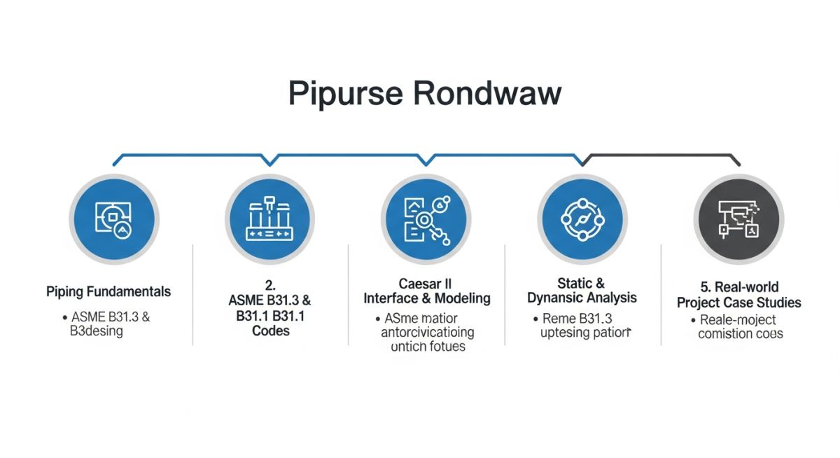
What Does This Piping Stress Analysis Caesar II Course Cover?
To give you a clear picture of what you will master, the table below outlines the standard load case setup matrix that we build and analyze during the practical sessions of the course.
| Load Case No. | Caesar II Load Case | Type | Description | Code Compliance |
|---|---|---|---|---|
| L1 | W+P1+T1 | OPE | Operating Case (Weight + Pressure + Thermal) | Nozzle Load Check |
| L2 | W+P1 | SUS | Sustained Case (Weight + Pressure) | ASME B31.3 Stress Check |
| L3 | L1-L2 | EXP | Expansion Case (Thermal Range) | ASME B31.3 Stress Check |
| L4 | W+P1+T1+Win | OCC | Occasional Case (Operating + Wind) | ASME B31.3 Stress Check |
Understanding the core entities and physical parameters is fundamental to navigating the software interface and interpreting the output reports.
| Entity / Acronym | Technical Definition | Physical Parameter | Standard Reference |
|---|---|---|---|
| SIF | Stress Intensification Factor | Dimensionless fatigue multiplier | ASME B31.3 Appendix D |
| W | Pipe Weight (including fluid and insulation) | Force per unit length | ASME B31.3 Section 301.3 |
| P | Design Pressure | Force per unit area | ASME B31.3 Section 301.2 |
| T | Design Temperature | Degrees Celsius or Fahrenheit | ASME B31.3 Section 301.1 |
| E | Modulus of Elasticity | Force per unit area (GPa or Mpsi) | ASME B31.3 Table C-6 |
How to Verify Caesar II Model Outputs?
Before submitting any stress analysis report for construction, I always insist on a rigorous verification process. Below is the exact checklist I use on my projects to ensure the model matches physical reality.
-
✓
Verify material properties (Elastic modulus, thermal expansion coefficient) match the design temperature. -
✓
Confirm boundary conditions (anchors, guides, spring hangers) reflect actual structural support designs. -
✓
Check that all equipment nozzle loads are within allowable limits specified by API 610 or API 617. -
✓
Validate that the stress intensification factors (SIFs) are correctly applied to tees, elbows, and branch connections. -
✓
Ensure occasional load cases (wind, seismic) are configured with the correct regional design parameters.
Field Case Study: Real-World Application
This case highlights why practical training is so valuable. In our course, we analyze real-world failures like this one, teaching you how to identify design flaws before they reach the construction phase.

Frequently Asked Engineering Questions
What is the difference between sustained and expansion stress in Caesar II?
How does Caesar II calculate stress intensification factors (SIFs)?
When should I use variable spring hangers instead of rigid supports?
How do I handle equipment nozzle load limits in Caesar II?
What is the significance of the stress range reduction factor (f)?
Can Caesar II perform dynamic analysis for water hammer events?
===
📚 Recommended Resources: piping stress analysis caesar ii course
Read these Guides
🎓 Advanced Training


Related posts:
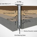
![Cross-section diagram showing a steel solar pile foundation embedded in layered soil profiles for structural analysis.]()
Essential Geotechnical Pile Design Data for Utility-Scale Solar Structures
![Professional surveyor conducting Topographical Surveys for Solar Projects on a large-scale utility site with complex terrain.]()
Topographical Surveys for Solar Projects: A Technical Engineering Guide
![A geotechnical drill rig performing soil sampling on a large, open field intended for a utility-scale solar farm project.]()
Geotechnical Investigation for Solar Farms: Essential Site Design Guide
![Isometric site plan showing Utility Corridor Planning for Data Centres with color-coded power, water, and telecom infrastructure paths.]()
Utility Corridor Planning for Data Centres: A Strategic Engineering Guide
![Aerial view of a data centre site showcasing perimeter drainage systems, detention basins, and site grading for flood prevention.]()
Drainage Design Considerations for Data Centres: A Technical Guide
![Professional surveyor using a Total Station on a large data centre construction site for topographical mapping.]()
Topographical Surveys for Data Centre Projects: A Technical Guide