
What Are Spool Valves and How Do They Work
In my 20 plus years of piping and fluid power engineering, I have seen many systems fail not because of massive pipe ruptures, but because of tiny, microscopic issues inside the control elements. The spool valve is the unsung workhorse of industrial automation. If you have ever watched an excavator lift a multi-ton load with pinpoint precision, you have witnessed a spool valve managing thousands of pounds per square inch of fluid pressure. Let me take you through the gritty realities of designing, selecting, and troubleshooting these components.
Key Takeaways
- Precision clearances (typically two to eight microns) are the primary defense against internal leakage.
- Hydraulic lock caused by pressure imbalances can completely seize a spool if balancing grooves are omitted.
- Material selection must pair hard spools with slightly softer bores to prevent galling and catastrophic seizing.
- Proper filtration is non-negotiable; particulate contamination is the number one killer of spool-based systems.
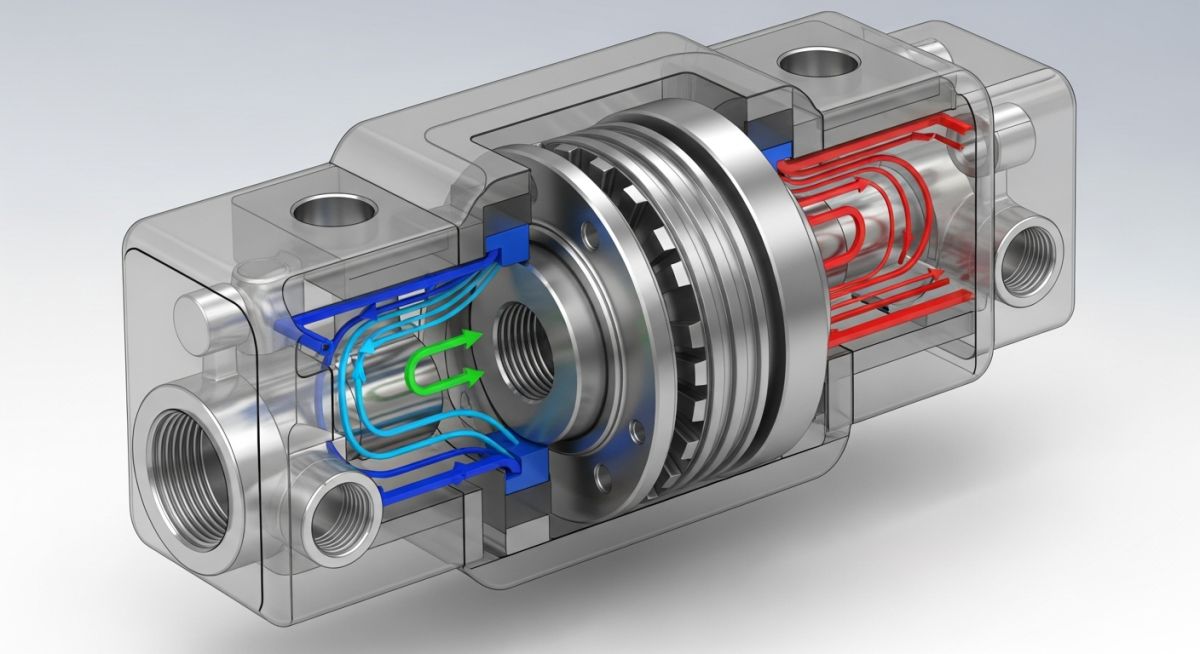
To truly understand how these valves operate, we must look at their internal geometry. A spool valve consists of a cylindrical shaft (the spool) that slides axially or rotates within a machined housing (the bore). The spool features larger diameter sections called lands and smaller diameter sections called grooves. The lands physically block fluid flow by sealing against the bore walls, while the grooves allow fluid to pass around the spool and exit through designated ports.
In my experience, the design of these lands is a delicate balancing act. The overlap between the land and the port (known as spool overlap) dictates the valve’s response time and leakage characteristics. An under-lapped spool allows immediate flow but suffers from high standby leakage. An over-lapped spool minimizes leakage but introduces a deadband where no flow occurs during initial movement.
Calculating Leakage and Forces in Spool Design
Internal leakage is a major drawback of spool valves. Because there is no elastomeric seal between the sliding spool and the bore, we rely entirely on a micro-clearance fit. We can calculate this leakage using the Hagen-Poiseuille equation for flow through an annular gap:
Where:
- Q = Leakage flow rate (cubic meters per second)
- D = Spool diameter (meters)
- c = Radial clearance (meters)
- dP = Pressure differential (Pascals)
- mu = Dynamic viscosity of the fluid (Pascal-seconds)
- L = Land contact length (meters)
- e = Eccentricity ratio (dimensionless, ranging from 0 to 1)
Let us look at a real-world example. Consider a spool with a diameter of 20 millimeters, a radial clearance of 5 microns (0.000005 meters), operating at a pressure differential of 210 bar (21,000,000 Pascals). The fluid is an ISO VG 46 hydraulic oil with a dynamic viscosity of 0.03 Pascal-seconds at operating temperature. The land length is 15 millimeters. Assuming a perfectly concentric spool (eccentricity equals zero):
Q = (0.06283 * 1.25 * 10^-16 * 21 * 10^6) / 0.0054
Q = 1.649 * 10^-10 / 0.0054
Q = 3.05 * 10^-8 cubic meters per second (approximately 1.83 milliliters per minute)
If the spool becomes fully eccentric (eccentricity equals one) due to side-loading, the leakage increases by a factor of 2.5, jumping to over 4.5 milliliters per minute. This highlights why maintaining spool concentricity is so critical.

Key Design Considerations for Spool Valves Engineering
When designing or selecting these valves, we must account for flow forces. As fluid flows through the metering orifices of the valve, it accelerates, creating a localized drop in static pressure. This generates a Bernoulli force (often called the flow force) that acts on the spool, typically trying to pull the spool closed.
The steady-state flow force can be estimated using:
Where Cd is the discharge coefficient (typically around 0.6 to 0.62), A is the orifice area, dP is the pressure drop across the land, and theta is the jet angle (usually around 69 degrees). In high-flow systems, these forces can exceed 100 Newtons, requiring robust solenoids or pilot-operated designs to overcome them.
The table below outlines typical radial clearances and acceptable leakage rates for industrial spool valves operating under standard conditions. These values are critical for sizing hydraulic power units and determining system efficiency.
| Spool Diameter (mm) | Radial Clearance (microns) | Max Pressure (bar) | Allowable Leakage (mL/min) | ISO 4406 Cleanliness |
|---|---|---|---|---|
| 10 to 15 | 2 to 4 | 315 | 0.5 to 1.5 | 17/15/12 |
| 16 to 25 | 4 to 6 | 350 | 1.5 to 3.0 | 18/16/13 |
| 26 to 40 | 6 to 10 | 420 | 3.0 to 8.0 | 19/17/14 |
This matrix maps core technical entities, structural acronyms, and physical parameters to their respective industry standards. Use this as a reference when drafting procurement specifications.
| Entity / Parameter | Acronym | Primary Function | Standard Reference |
|---|---|---|---|
| Directional Control Valve | DCV | Directs fluid path to actuators | ISO 4401 |
| Rockwell Hardness C | HRC | Measures wear resistance of spool steel | ASTM E18 |
| Fluid Power Systems | FPS | General system design guidelines | ISO 4413 |
| National Fluid Power Association | NFPA | Establishes pressure rating standards | NFPA T3.5.1 |
In my years on-site, I have found that over ninety percent of premature valve failures can be traced back to poor installation practices. Use this checklist before powering up any newly installed or serviced spool valve assembly.
Pre-Commissioning Verification Steps
-
Manifold Flatness Check: Verify that the mounting manifold flatness is within 0.01 millimeters per 100 millimeters of run to prevent body distortion when bolted down.
-
Torque Specification: Tighten mounting bolts in a cross-pattern sequence to the exact manufacturer-specified torque. Over-tightening will distort the bore and cause the spool to stick.
-
Fluid Cleanliness Verification: Pull a fluid sample and verify that the ISO 4406 cleanliness level matches or exceeds the valve requirement (typically 18/16/13 for standard proportional spools).
-
Solenoid Alignment: Ensure solenoid coils are fully seated and the retaining nut is torqued correctly. Loose coils can overheat and burn out rapidly.
-
Pilot Pressure Verification: Confirm that pilot pressure lines are set to the minimum required pressure to shift the spool under full system load.
Field Case Study: Real-World Application
The Problem: Intermittent Spool Seizing
A heavy manufacturing plant operating a 350-bar hydraulic forging press experienced intermittent spool sticking on its primary directional control valve. The valve would seize after approximately four hours of continuous operation, causing costly production delays. The maintenance team replaced the valve twice, but the issue recurred within days.
The Outcome: Thermal Expansion and Clearance Optimization
I was called in to perform a forensic analysis. We discovered that the system fluid temperature rose from 30 degrees Celsius to 65 degrees Celsius during operation. The spool, made of hardened tool steel, expanded faster than the cast iron valve body due to different thermal expansion coefficients and localized flow heating. This reduced the 4-micron radial clearance to zero, causing thermal seizing.
The solution involved machining three 0.5-millimeter wide circumferential balancing grooves on the spool lands, increasing the cold radial clearance to 6 microns, and installing a water-glycol heat exchanger to cap fluid temperature at 50 degrees Celsius. The system has now run for over 18 months without a single sticking incident.
My direct recommendation for any high-duty cycle system is to always specify valves with circumferential balancing grooves. These grooves not only equalize pressure around the spool to prevent hydraulic lock, but they also act as traps for tiny contaminants, preventing them from wedging into the clearance gap.
Frequently Asked Engineering Questions
What is the primary difference between a spool valve and a poppet valve?
How do circumferential balancing grooves prevent hydraulic lock?
What causes a spool valve to stick or seize during operation?
Can spool valves be used for proportional flow control?
How does fluid viscosity affect spool valve performance?
What are the standard mounting interfaces for industrial spool valves?
===FAQ_BLOCK===
Related posts:
![Cross-section diagram showing a steel solar pile foundation embedded in layered soil profiles for structural analysis.]()
Essential Geotechnical Pile Design Data for Utility-Scale Solar Structures
![Professional surveyor conducting Topographical Surveys for Solar Projects on a large-scale utility site with complex terrain.]()
Topographical Surveys for Solar Projects: A Technical Engineering Guide
![A geotechnical drill rig performing soil sampling on a large, open field intended for a utility-scale solar farm project.]()
Geotechnical Investigation for Solar Farms: Essential Site Design Guide
![Isometric site plan showing Utility Corridor Planning for Data Centres with color-coded power, water, and telecom infrastructure paths.]()
Utility Corridor Planning for Data Centres: A Strategic Engineering Guide
![Aerial view of a data centre site showcasing perimeter drainage systems, detention basins, and site grading for flood prevention.]()
Drainage Design Considerations for Data Centres: A Technical Guide
![Professional surveyor using a Total Station on a large data centre construction site for topographical mapping.]()
Topographical Surveys for Data Centre Projects: A Technical Guide