Table of Contents

What is a Neoprene Pad? Properties and Structural Applications
Over my 20 years in piping and structural engineering, I have seen minor design oversights lead to catastrophic structural failures. One component that is frequently underestimated is the humble elastomeric bearing. In my experience, engineers often treat these pads as simple pieces of rubber, ignoring the complex polymer chemistry and structural mechanics that allow them to protect multi-million dollar bridges and industrial facilities.
When you are dealing with thermal expansion, seismic shifts, or high-frequency vibrations, selecting the correct durometer and shape factor is the difference between a structure that lasts for a century and one that suffers from premature concrete spalling. Let us break down the exact engineering parameters, material properties, and field realities of these critical components.
- Understanding how shape factor controls compressive strain and prevents bulging failure.
- Selecting the correct durometer (typically 50 to 70 Shore A) based on load and rotation requirements.
- Ensuring compliance with AASHTO M251 and ASTM D4014 to guarantee long-term ozone and shear resistance.
Complete Course on
Piping Engineering
Check Now
Key Features
- 125+ Hours Content
- 500+ Recorded Lectures
- 20+ Years Exp.
- Lifetime Access
Coverage
- Codes & Standards
- Layouts & Design
- Material Eng.
- Stress Analysis
Understanding the Engineering Mechanics of a Neoprene Pad
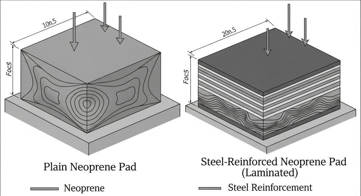
To design a reliable elastomeric bearing, we must first analyze its shape factor. The shape factor is a dimensionless ratio that directly influences how the elastomer behaves under vertical compression. Because rubber is virtually incompressible in terms of volume, it must bulge laterally when subjected to vertical loads. If we restrict this bulging, we increase the compressive stiffness of the pad.
The shape factor (S) of a rectangular pad is calculated using the following formula:
Where:
• Width is the transverse dimension of the pad.
• Length is the longitudinal dimension of the pad.
• Thickness is the thickness of a single elastomer layer.
In my experience, a higher shape factor results in less vertical deflection and higher load-bearing capacity. However, it does not alter the shear stiffness of the pad. The shear stiffness is governed solely by the plan area and the total elastomer thickness, which allows us to decouple the vertical load capacity from the horizontal thermal movement capacity.
Never substitute commercial-grade neoprene for structural-grade chloroprene. Commercial neoprene often contains high levels of carbon black fillers and recycled rubber, which drastically reduces ozone resistance and leads to rapid environmental degradation and cracking under sustained structural loads. Always demand certified test reports complying with ASTM D4014.
Under the AASHTO LRFD Bridge Design Specifications, design engineers can utilize either Method A or Method B for elastomeric bearing design. Method A is simpler but limits the average compressive stress to 5.5 MPa (800 psi) for plain pads. Method B allows for higher compressive stresses up to 11.0 MPa (1600 psi) for steel-reinforced pads but requires rigorous testing and tighter quality control.
The physical properties of structural neoprene are tightly regulated to ensure long-term durability under harsh environmental conditions. Below is the standard engineering data for structural-grade chloroprene elastomers across different durometer ratings.
| Physical Property | Test Method | 50 Durometer | 60 Durometer | 70 Durometer |
|---|---|---|---|---|
| Hardness (Shore A) | ASTM D2240 | 50 +/- 5 | 60 +/- 5 | 70 +/- 5 |
| Min. Tensile Strength | ASTM D412 | 15.5 MPa | 15.5 MPa | 15.5 MPa |
| Min. Elongation at Break | ASTM D412 | 400% | 350% | 300% |
| Max. Compression Set (22h @ 100°C) | ASTM D395 | 35% | 35% | 35% |
| Ozone Resistance (100 pphm, 100h @ 40°C) | ASTM D1149 | No Cracks | No Cracks | No Cracks |
| Entity / Acronym | Physical Parameter | Structural Function | Standard Reference |
|---|---|---|---|
| S (Shape Factor) | Dimensionless Ratio | Controls compressive stiffness and bulging | AASHTO LRFD Section 14 |
| G (Shear Modulus) | 0.8 to 1.2 MPa | Determines horizontal shear stiffness | ASTM D4014 |
| PEP (Plain Elastomeric Pad) | Unreinforced | Accommodates small loads and rotations | AASHTO M251 |
| SRC (Steel-Reinforced Pad) | Laminated with steel plates | Handles high compressive loads and rotations | ASTM D4014 Class A |
Quality Control Checklist for Neoprene Pad Installation
Even the most precisely designed bearing will fail if the field installation is executed poorly. In my experience, improper seating is the leading cause of localized stress concentrations and premature concrete spalling. Use this checklist on your job site to verify compliance before casting or placing structural elements.
-
Substructure Surface Preparation: Ensure the concrete seat is level within 0.002 radians and free of voids, laitance, or projecting aggregate.
-
Pad Alignment and Orientation: Verify that the long axis of the pad is aligned parallel to the transverse axis of the girder to accommodate longitudinal thermal expansion.
-
Temperature Correction: Adjust the placement offset of the pad based on the ambient installation temperature relative to the mean design temperature.
-
Uniform Contact Verification: Check for any gaps between the pad and the girder sole plate using a 0.05 mm feeler gauge; no gaps are permitted.
-
Anchor Bolt Clearance: Ensure that anchor bolts do not bind against the elastomeric pad or restrict the free shear deformation of the bearing.
Field Case Study: Real-World Application
During a routine inspection of a 15-year-old highway overpass, I observed severe concrete spalling at the bridge abutments and visible tearing in several elastomeric bearings. The original contractor had substituted commercial-grade neoprene pads for the specified AASHTO M251 structural-grade pads. The high carbon black content and lack of proper anti-ozonants caused the pads to harden prematurely, increasing their shear modulus by over 150%. This restricted the thermal expansion of the concrete prestressed girders, transferring massive horizontal forces directly into the concrete abutments and causing structural cracking.
I led the engineering team that designed the jacking procedure to lift the bridge deck by 12 mm under live traffic conditions. We replaced the degraded commercial pads with custom-engineered, steel-reinforced neoprene pads (60 Durometer, Shape Factor of 6.5) complying with ASTM D4014. Post-installation monitoring over the next two seasonal thermal cycles confirmed that the horizontal shear forces were fully absorbed by the new bearings, completely stabilizing the concrete abutments and preventing further structural degradation.
This project highlighted the critical importance of material specification. I highly recommend that field engineers always verify the manufacturer’s certified test reports (MTRs) for physical properties and ozone resistance before allowing any elastomeric bearing to be cast or placed on site.
Frequently Asked Engineering Questions
What is the difference between a plain neoprene pad and a steel-reinforced elastomeric bearing?
How does the shape factor affect the performance of a neoprene pad?
Can neoprene pads be used for vibration isolation in industrial machinery?
What is the typical lifespan of a structural neoprene pad?
How do temperature extremes affect the properties of neoprene?
Why is durometer hardness critical when selecting a neoprene pad?

📚 Recommended Resources: Neoprene Pad
Related posts:
![Comparison of raw PTFE material and an industrial PTFE-lined steel pipe flange]()
Teflon vs PTFE: Major Differences in Industrial Piping Applications
![Severe metal galling damage on a stainless steel threaded bolt and nut.]()
What is Metal Galling and How to Prevent It
![Certified welder performing structural welding repair on a heavy steel beam with sparks flying.]()
Mastering Industrial Welding Repair Procedures for Structural Integrity
![A fully assembled industrial pump skid system with stainless steel piping and control panels in a factory.]()
What is an Industrial Pump Skid and Its Key Advantages?
![Side-by-side comparison of an industrial flow meter and a digital flow transmitter installed on a pipeline.]()
Flow Transmitter vs Flow Meter: Key Differences Explained
![Wireless vibration sensor mounted on an industrial electric motor for condition monitoring.]()
What is Vibration Monitoring and Why is it Important?