Table of Contents
What is a Golden Joint in Piping Systems?
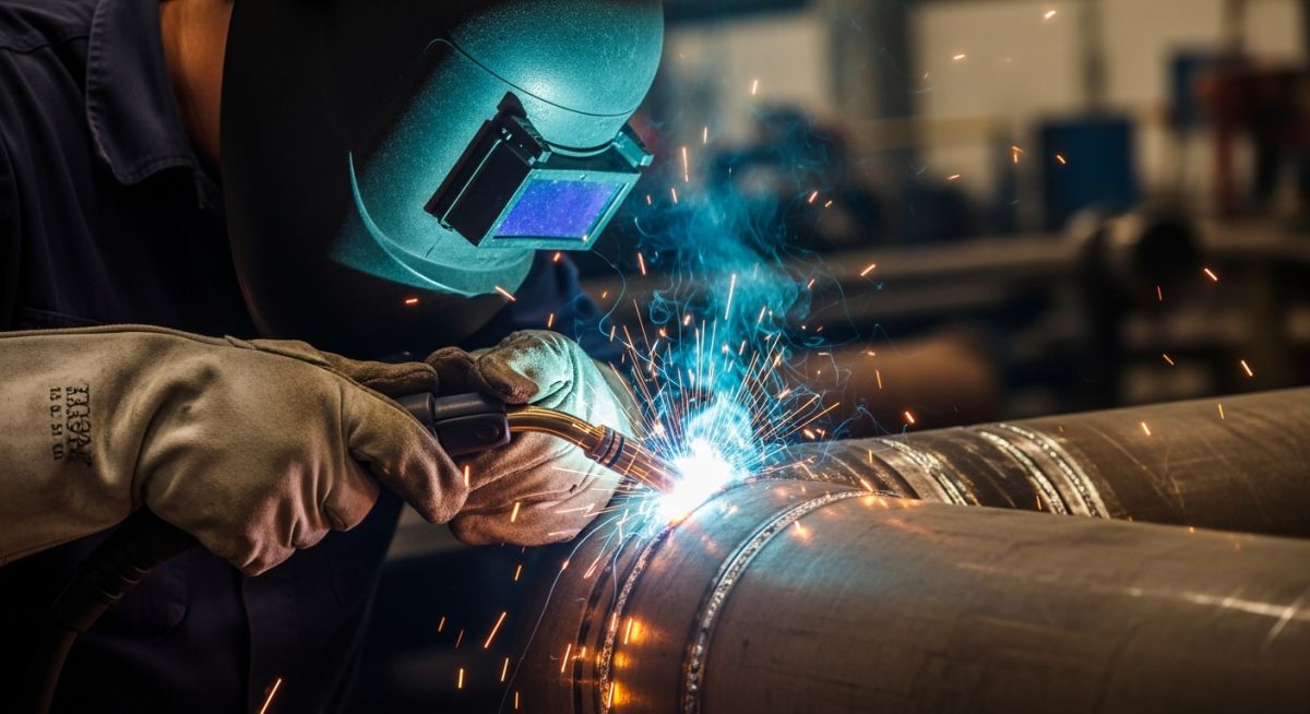
In my 20 years of managing piping construction projects, nothing makes a field engineer hold their breath quite like a tie-in weld that cannot be hydrostatically tested. We call this a golden joint. When you are connecting a new process unit to an existing, live refinery header, filling the entire system with water is simply not an option. Over the years, I have seen how a single oversight on these untested welds can lead to catastrophic field failures, which is why the industry treats them with absolute reverence.
Key Engineering Takeaways
- A golden joint is a regulatory deviation that must be backed by a formal risk assessment and client approval.
- Standard hydrostatic leak testing is replaced by a combination of 100% volumetric and surface non-destructive examinations (NDT).
- Welder qualification and weld preparation tolerances are significantly tighter than standard production welds.
- The primary governing code for process piping golden joints is ASME B31.3 Section 345.9.
Why is a Golden Joint Welded This Way?
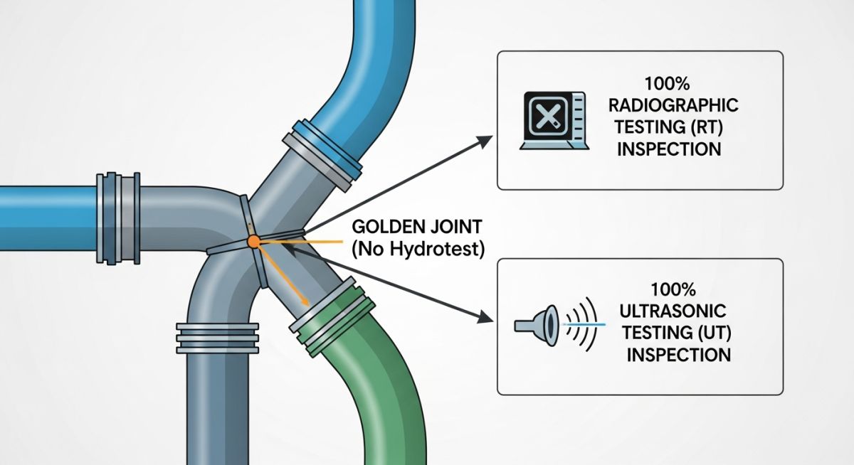
Golden Joint Application: The execution of a golden joint relies on substituting volumetric and surface non-destructive examinations for the standard hydrostatic leak test. This engineering deviation is strictly controlled under ASME B31.3 Section 345.9 to ensure the structural integrity of the final tie-in weld.
To understand why we use a golden joint, we must first look at the physics of a standard hydrostatic test. A hydrotest subjects the piping system to 1.5 times (or 1.1 times for pneumatic tests) the design pressure. This stress-tests the material and mechanical joints, causing localized yielding at stress concentration points, which actually helps redistribute stresses.
However, when we perform a final tie-in to an operating plant, hydrotesting is often physically impossible. For example, introducing water into a catalytic cracking unit would ruin millions of dollars of catalyst. In gas transmission lines, drying out the pipe after a hydrotest to prevent hydrate formation can take weeks. In these scenarios, we design a golden joint.
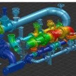
Stress and Load Calculations for Tie-In Welds
Because a golden joint does not benefit from the mechanical “stress relief” of a hydrotest, we must perform rigorous stress analysis. The longitudinal stress (SL) at the joint must be calculated to ensure it does not exceed the allowable stress limits of the material.
SL = (P * D) / (4 * t) + (M / Z)
Where:
– P = Internal design pressure (psi)
– D = Outside diameter of the pipe (inches)
– t = Nominal wall thickness minus corrosion allowance (inches)
– M = Bending moment from thermal expansion and weight (inch-pounds)
– Z = Section modulus of the pipe (cubic inches)
Under ASME B31.3, the sum of the longitudinal stresses due to sustained loads (pressure and weight) and displacement strains (thermal expansion) must be carefully balanced. If the calculated stress exceeds 90% of the allowable stress (Sh) at design temperature, we must modify the piping layout to add flexibility before executing the weld.
The Multi-Layer NDT Protocol
Since we cannot pressure test the joint, we must inspect it with absolute precision. This is achieved through a multi-layer non-destructive testing (NDT) protocol:
- Root Pass Inspection: 100% Liquid Penetrant Testing (PT) or Magnetic Particle Testing (MT) to detect any micro-cracking or lack of fusion in the critical first pass.
- Hot Pass and Fill Passes: Visual inspection of each weld layer by a certified welding inspector.
- Completed Weld Surface: 100% PT or MT on the final weld cap to check for surface defects, undercut, or porosity.
- Volumetric Examination: 100% Radiographic Testing (RT) or Phased Array Ultrasonic Testing (PAUT) to inspect the internal structure of the weld. PAUT is highly preferred today as it provides a digital record of the weld volume and is excellent at sizing planar defects.
Golden Joint Code Compliance: International piping codes establish strict boundaries for when and how alternative leak testing can replace a hydrostatic test. The table below outlines the specific NDT requirements and code sections for different piping applications.
| Piping Code | Application | Code Section | Mandatory NDT Requirements |
|---|---|---|---|
| ASME B31.3 | Process Piping (Refineries, Chemical Plants) | Section 345.9 (Alternative Leak Test) | 100% RT or 100% UT, plus 100% PT or MT on root and final weld cap. |
| ASME B31.1 | Power Piping (Steam, Boiler Systems) | Section 345.9 (Alternative Leak Test) | 100% RT or UT, with strict pre-heating and post-weld heat treatment (PWHT) monitoring. |
| ASME B31.4 | Liquid Pipeline Transportation Systems | Section 437.1.4 (Testing of Tie-Ins) | 100% visual inspection and 100% radiographic or ultrasonic examination. |
| ASME B31.8 | Gas Transmission and Distribution Pipelines | Section 841.3.2 (Tie-In Testing) | 100% NDT (RT or UT) for all welds not subjected to strength tests. |
| Technical Entity | Acronym | Physical Parameter / Limit | Standard Reference |
|---|---|---|---|
| Phased Array Ultrasonic Testing | PAUT | Zero planar defects allowed | ASME Section V Article 4 |
| Post-Weld Heat Treatment | PWHT | Temperature hold based on material thickness | ASME B31.3 Table 331.1.1 |
| Welder Performance Qualification | WPQ | Must be qualified for specific position and process | ASME Section IX |
| Welding Procedure Specification | WPS | Qualified with impact testing if required | ASME Section IX |
How to Inspect a Golden Joint Safely?
Golden Joint Inspection Protocol: Safe inspection of a golden joint requires a multi-stage quality control workflow that validates material chemistry, welder qualifications, fit-up tolerances, and multi-pass non-destructive testing. This systematic validation ensures the weld achieves a zero-defect state before being placed into high-pressure service.
In my experience, the secret to a successful golden joint is not just the skill of the welder, but the discipline of the inspection team. We must treat the weld as a series of hold points. If any single step fails to meet the criteria, the entire process must stop immediately.
Field Quality Control Checklist
-
Step 1: Engineering Authorization
Verify that a formal deviation request has been signed off by the client’s technical authority and the lead piping engineer.
-
Step 2: Welder Qualification Verification
Confirm the welder holds a current WPQ under ASME Section IX specifically for the pipe diameter, wall thickness, and welding process (e.g., GTAW for root, SMAW for fill).
-
Step 3: Positive Material Identification (PMI)
Perform PMI on both pipe ends and the welding filler wire to ensure material chemistry matches the design specifications.
-
Step 4: Fit-Up and Bevel Inspection
Measure the root gap, root face, and bevel angle. Misalignment (high-low) must not exceed 1.5 mm (1/16 inch).
-
Step 5: Root Pass NDT Hold Point
Perform 100% PT or MT on the root pass. No linear indications or cracks are permitted.
-
Step 6: Final Volumetric NDT
Execute 100% PAUT or RT on the completed weld. The acceptance criteria must be “zero defects” (severe than standard production welds).
Field Case Study: Real-World Application
Field Case Study Analysis: This field case study examines the execution of a high-pressure tie-in weld on a live refinery header without a hydrostatic test. It demonstrates how strict adherence to alternative leak testing protocols prevents catastrophic field failures.
The Problem: High-Pressure Gas Tie-In
During a major refinery expansion in 2024, our team had to tie a new 24-inch carbon steel gas line (Class 600) into an existing operating header. A standard hydrostatic test would have flooded the downstream catalyst beds, causing millions of dollars in damage. The tie-in weld had to be executed as a golden joint under extreme schedule pressure.
The Outcome: Zero-Defect Execution
We implemented a strict golden joint protocol. We utilized a highly experienced welder qualified under ASME Section IX, performed 100% root-pass PT, and completed the weld with 100% PAUT. The joint passed all inspections on the first attempt. The line has now been operating at 980 psi for over two years without a single micro-fissure or leak.
My direct recommendation for any project manager facing a similar situation is to invest in the best welding crew and NDT technicians available. The cost of premium labor is a fraction of the cost of a weld repair on a live system.
Frequently Asked Engineering Questions
Golden Joint FAQ Reference: This technical FAQ reference provides direct, code-compliant answers to the most common questions regarding the design, execution, and inspection of untested tie-in welds. All answers align with ASME B31.3 and API 1104 standards.
What is the difference between a golden joint and a standard tie-in weld?
Is a golden joint permitted under ASME B31.3?
Why is PAUT preferred over RT for golden joint inspection?
Can a socket weld be classified as a golden joint?
What happens if a golden joint fails NDT?
Is client approval mandatory for executing a golden joint?
Complete Course on
Piping Engineering
Check Now
Key Features
- 125+ Hours Content
- 500+ Recorded Lectures
- 20+ Years Exp.
- Lifetime Access
Coverage
- Codes & Standards
- Layouts & Design
- Material Eng.
- Stress Analysis

📚 Recommended Resources: golden joint
Related posts:
![Super duplex stainless steel piping network on an offshore oil drilling platform.]()
Super Duplex Stainless Steel Oil and Gas Piping Design Guide
![Industrial duplex stainless steel piping system in a chemical processing facility.]()
Understanding Duplex Stainless Steel Properties and Industrial Piping Applications
![A collection of different types of industrial pipes classified by material and size on a storage rack.]()
Comprehensive Guide to Types of Pipes and Industrial Classification Systems
![Industrial piping network with digital overlays representing inch-dia and inch-meter engineering calculations.]()
What are Inch-Dia and Inch-Meter in Piping Systems?
![3D finite element stress analysis model of an industrial piping system showing stress distribution.]()
What Causes Piping System Stresses in Industrial Plants?
![Industrial piping system featuring a large U-shaped pipe expansion loop on an elevated rack.]()
How to Design Pipe Expansion Loops for Piping Systems