Table of Contents
Automatic Recirculation Valve Guide for Centrifugal Pump Protection
In my 20 years of commissioning high-pressure boiler feed pumps and hydrocarbon transfer systems, I have seen many plants suffer catastrophic pump failures. These failures almost always stem from a common operational hazard: running a centrifugal pump below its minimum continuous stable flow (MCSF). When process demand drops, the energy input from the impeller is converted entirely into heat, leading to rapid vaporization, dry running, and mechanical seal destruction.
While traditional systems rely on complex multi-component control loops—consisting of flow transmitters, controllers, and pneumatic control valves—the Automatic Recirculation Valve (ARV) offers an elegant, self-acting alternative. It combines a non-return valve, a flow sensing mechanism, and a pressure-reducing bypass valve into a single, robust body. In this guide, I will share my field experience on how these valves operate, how to size them, and how to avoid common installation pitfalls.
Key Engineering Takeaways
- Understand how the mechanical linkage between the main check valve disk and the bypass trim eliminates the need for external power or instrumentation.
- Learn the mathematical relationship between pump temperature rise and minimum flow requirements.
- Identify the critical differences between continuous bypass systems and modulating ARV systems.
- Master the installation best practices to prevent cavitation and flashing in the bypass recirculation line.
Complete Course on
Piping Engineering
Check Now
Key Features
- 125+ Hours Content
- 500+ Recorded Lectures
- 20+ Years Exp.
- Lifetime Access
Coverage
- Codes & Standards
- Layouts & Design
- Material Eng.
- Stress Analysis
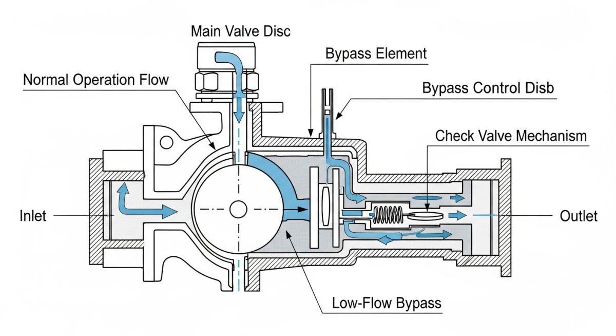
How an Automatic Recirculation Valve Protects Pumps
The heart of the ARV is its check valve disk, which is positioned directly in the main process flow path. This disk is spring-loaded and moves vertically in response to the volumetric flow rate passing through the valve. When process demand is high, the flow forces the disk upward into the fully open position. This mechanical movement is transmitted via a lever or stem linkage to the bypass valve spindle.
As the main disk rises, the linkage forces the bypass valve plug to close against its seat. Conversely, when the process demand drops and the main flow decreases, the spring pushes the main disk back down toward its seat. This downward movement pulls the bypass plug open, allowing a predetermined minimum flow to recirculate back to the suction vessel or deaerator.
In high-pressure systems, such as boiler feed water applications, the pressure drop across the bypass trim can be massive. If the bypass line is not designed with adequate backpressure, the fluid will flash into steam as it passes through the bypass valve. This leads to severe erosion of the valve trim and piping. Always ensure the bypass line discharges below the liquid level of the supply vessel or install a multi-stage pressure reduction orifice.
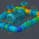
Thermodynamic Calculations for Minimum Flow
To size an ARV, we must first calculate the minimum continuous stable flow (Q_{min}) required to limit the temperature rise (Delta T) of the fluid within the pump. The temperature rise can be calculated using the following thermodynamic formula:
Where:
- ΔT = Temperature rise of the fluid (°C)
- P = Pump shaft power at the operating point (kW)
- η = Pump efficiency at the operating point (decimal)
- C_p = Specific heat capacity of the fluid (kJ/kg·°C)
- ρ = Density of the fluid (kg/m³)
- Q = Flow rate through the pump (m³/s)
By setting the maximum allowable temperature rise (typically 5°C to 8°C for water to prevent flashing at the impeller eye), we can solve for the minimum flow rate (Q_{min}). This calculated value dictates the sizing of the ARV’s bypass trim. All designs must comply with API 610 design criteria for centrifugal pumps.
Selecting an Automatic Recirculation Valve System
When specifying an ARV, engineers must choose between a modulating bypass and an on-off bypass. Modulating bypass valves are highly preferred for high-capacity systems because they only bypass the exact deficit between the actual process flow and the MCSF. This saves significant pumping energy compared to on-off designs, which dump the full minimum flow into the bypass line as soon as the valve triggers.
Furthermore, the valve body and internals must be selected to withstand the design pressure and temperature of the system in accordance with ASME B16.34. For corrosive or erosive fluids, hardened trim materials like Stellite or tungsten carbide are mandatory to prevent premature wear of the modulating bypass plug.
The following tables provide standard engineering reference data for selecting and sizing automatic recirculation valves in industrial piping systems.
Table 1: Typical ARV Material Selection Guidelines
| Service Fluid | Body Material | Trim Material | Applicable Standard |
|---|---|---|---|
| Boiler Feed Water | ASTM A216 WCB / A105 | 410 SS with Stellite Facing | ASME B16.34 |
| Hydrocarbons / Crude Oil | ASTM A352 LCC / A350 LF2 | 316 SS / Duplex SS | API 610 |
| Sea Water / Desalination | Super Duplex SS (A890) | Super Duplex / Ceramic | NACE MR0175 |
Table 2: Technical Mapping & Specifications Matrix
| Parameter / Entity | Acronym | Physical Unit | Design Significance |
|---|---|---|---|
| Minimum Continuous Stable Flow | MCSF | m³/h or gpm | The baseline flow below which the ARV bypass must open to prevent pump damage. |
| Net Positive Suction Head Required | NPSHr | m or ft | Increases rapidly at low flows; ARV prevents pump from operating in this zone. |
| Bypass Pressure Drop | ΔP_bypass | bar or psi | Determines the number of pressure reduction stages required in the bypass trim. |
Commissioning Your Automatic Recirculation Valve Correctly
During plant commissioning, the ARV is often subjected to construction debris, piping misalignment stresses, and improper bypass line routing. To ensure trouble-free operation, I always enforce a strict field verification protocol before the first pump start.
Pre-Commissioning Field Checklist
-
Piping Strain Verification: Ensure that the piping connected to the ARV is fully supported and does not transfer flange loads exceeding API 610 nozzle load limits. -
Bypass Line Routing: Confirm that the bypass line runs continuously downward to the receiver vessel without any high-point vapor pockets. -
Flushing Bypass Installation: Verify that a temporary startup strainer is installed upstream of the ARV to prevent welding slag from damaging the precision-machined bypass trim. -
Manual Isolation Valves: Ensure that any manual isolation valve on the bypass line is locked in the fully open position during normal operation. -
Backpressure Check: Confirm that the backpressure regulator or orifice plate in the bypass line is sized correctly for the minimum flow rate.
Field Case Study: Real-World Application
At a combined-cycle power plant in Southeast Asia, the 120 bar boiler feed water pumps were experiencing repeated thrust bearing failures and mechanical seal leaks. The existing system utilized a continuous bypass orifice line. Because the orifice was sized for the worst-case minimum flow, it constantly bypassed 25% of the pump’s capacity back to the deaerator, even when the plant was operating at 100% load. This resulted in massive energy waste, high fluid velocities, and severe cavitation at the orifice plate, which eventually eroded the bypass piping.
I recommended retrofitting the continuous bypass lines with modulating Automatic Recirculation Valves. The ARVs were sized to automatically close the bypass loop as soon as the main process demand exceeded the MCSF of 45 m³/h.
Upon installation, the plant achieved an immediate power savings of 110 kW per pump. Furthermore, the modulating design eliminated the high-velocity cavitation in the bypass line, extending the mean time between failures (MTBF) of the pump’s mechanical seals from 6 months to over 4 years.
This case highlights why relying on continuous bypass systems is highly inefficient for high-energy pumps. The capital cost of retrofitting to an ARV was fully recovered within just 9 months of operation solely through energy savings.
Frequently Asked Engineering Questions
Can an ARV be installed in a horizontal piping run?
What is the difference between an ARV and a pressure safety valve (PSV)?
How do you prevent cavitation in the ARV bypass trim?
Does an ARV require external electrical or pneumatic power?
Can an ARV handle fluids with high solid concentrations?
What standards govern the design of ARVs?

📚 Recommended Resources: Automatic Recirculation Valve
Related posts:
![Infographic flowchart of the GRP GRE FRP piping stress analysis workflow in START-PROF.]()
Rigid Struts: Definition, Applications, and Modeling in Caesar II
![3D stress analysis model of GRP piping system in START-PROF software showing stress distribution.]()
Stress Analysis of GRP / GRE / FRP Piping using START-PROF
![Industrial centrifugal pump installed on a concrete foundation with precision piping and alignment.]()
How to Use a Pump Installation Checklist for Maximum Reliability
![3D Caesar II pipe stress analysis model of a centrifugal pump piping system showing stress distribution.]()
Pump-Piping Alignment Caesar II Stress Analysis Methodology
![3D render of a structural steel cross-bracing connection with a gusset plate.]()
Mastering Steel Connections with a Cross-Bracing Design Example
![Industrial engineer checking shaft alignment on a centrifugal pump during commissioning.]()
How to Use a Pump Commissioning Checklist for Start-Up