How to Design and Install Vertical Pipe Support Systems
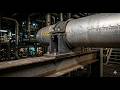
In my 20-plus years of designing piping systems for petrochemical plants and high-rise industrial facilities, I have seen many engineers treat vertical runs as an afterthought. They focus heavily on horizontal spans, only to realize that a 100-foot vertical steam riser exerts massive, concentrated loads at its base if not supported correctly. Supporting vertical pipes requires a completely different mindset than supporting horizontal runs. You cannot simply throw a standard hanger on a vertical line and expect it to work.
When you deal with vertical piping, you are fighting gravity directly along the pipe axis. Thermal expansion complicates this further; as the pipe heats up, it expands vertically, either lifting off its supports or overloading them. If your design fails to account for these forces, you risk buckling the pipe, overstressing equipment nozzles, or tearing structural steel. In this guide, I will share the exact calculations, code requirements, and field-tested strategies I use to design bulletproof vertical pipe support systems.
- Understand how to distribute deadweight loads across multiple floor levels using engineered riser clamps.
- Learn to calculate thermal expansion and select the correct spring hangers to prevent structural overloading.
- Discover how to apply ASME B31.3 and ASME B31.1 code requirements to vertical piping runs.
- Master the placement of anchors, guides, and limit stops to control directional pipe movement.
Complete Course on
Piping Engineering
Check Now
Key Features
- 125+ Hours Content
- 500+ Recorded Lectures
- 20+ Years Exp.
- Lifetime Access
Coverage
- Codes & Standards
- Layouts & Design
- Material Eng.
- Stress Analysis
Engineering Principles of Vertical Pipe Support
Vertical Pipe Support Engineering: The structural design process that calculates deadweight distribution, thermal growth, and friction forces to select appropriate riser clamps, spring hangers, and anchors.
To design an effective vertical support system, we must first analyze the forces at play. Unlike horizontal piping, where gravity acts perpendicular to the pipe axis, vertical piping experiences gravitational forces acting parallel to the pipe axis. This axial load must be transferred to the building structure safely.
Calculating Vertical Riser Loads
The first step is determining the total operating weight of the vertical run. This includes the bare pipe weight, the weight of the fluid inside, the insulation, and any inline components like valves or flanges. I use the following basic formula to calculate the total vertical load:
Where:
• W_pipe = Weight of the pipe per foot (lbs/ft)
• W_fluid = Weight of the process fluid per foot (lbs/ft)
• W_insulation = Weight of the insulation per foot (lbs/ft)
• L = Total vertical length of the riser (ft)
• W_components = Combined weight of valves, flanges, and instruments (lbs)
Once we have the total load, we must decide how to support it. If the load is small, a single riser clamp resting on a floor slab or structural steel frame may suffice. However, for heavy, multi-story risers, a single support point can overload the local structure. In these cases, we must distribute the load across multiple floors using spring hangers or multiple riser clamps.
Never use standard horizontal pipe clamps or U-bolts to support vertical loads. Standard clamps rely purely on friction and are not rated for axial loads. They will slip over time, causing the entire weight of the riser to crash down onto the bottom elbow, leading to catastrophic piping failure. Always specify dedicated riser clamps with integrated shear lugs welded to the pipe.
Managing Thermal Expansion in Risers
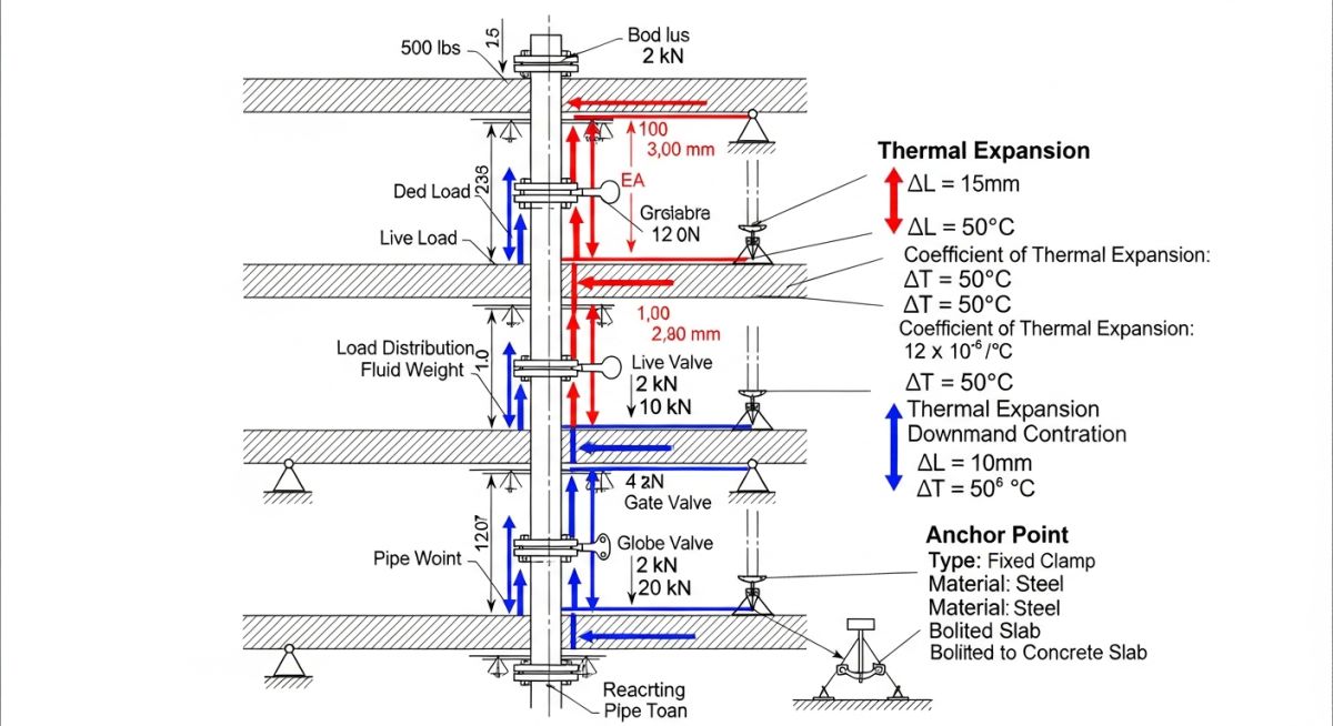
Thermal expansion is the most challenging aspect of vertical pipe design. When a vertical pipe heats up, it expands upward and downward from its anchor point. If the pipe is anchored at the bottom, the entire thermal growth occurs upward. If it is anchored at the top, the growth occurs downward.
To calculate the thermal expansion, we use the standard thermal growth formula:
Where alpha is the coefficient of thermal expansion for the pipe material, T_operating is the maximum operating temperature, and T_ambient is the installation temperature.
If we use rigid supports on a hot riser, the expanding pipe will lift off the upper supports, transferring all the weight to the bottom anchor. Conversely, if the pipe expands downward, it will overload the lower supports. To solve this, we must use variable spring hangers or constant support hangers. These devices use calibrated springs to maintain a relatively constant supporting force even as the pipe moves vertically.
When designing with springs, we must calculate the “spring variability.” According to ASME B31.3, the variability should ideally not exceed 25%. If the variability is too high, the change in support force during thermal movement will introduce excessive secondary stresses into the piping system.
The table below outlines the maximum recommended vertical support spacing for carbon steel and stainless steel pipes carrying water or steam, based on standard engineering practices and ASME B31.1 guidelines.
| Nominal Pipe Size (NPS) | Water Service Max Span (ft) | Steam/Gas Service Max Span (ft) | Typical Riser Clamp Rating (lbs) |
|---|---|---|---|
| 2″ (DN 50) | 14 | 18 | 1,200 |
| 4″ (DN 100) | 18 | 24 | 2,500 |
| 6″ (DN 150) | 22 | 30 | 4,000 |
| 8″ (DN 200) | 25 | 34 | 6,000 |
| 12″ (DN 300) | 30 | 40 | 10,500 |
This matrix maps the primary components used in vertical piping systems, their structural acronyms, physical parameters, and relevant industry standards.
| Support Component | Acronym | Primary Physical Parameter | Standard Reference |
|---|---|---|---|
| Riser Clamp | RC | Friction & Shear Load Capacity | MSS SP-58 Type 8 / 42 |
| Variable Spring Hanger | VSH | Spring Rate & Travel Range | MSS SP-58 Type 51 |
| Constant Support Hanger | CSH | Zero-Deviation Load Support | MSS SP-58 Type 54 |
| Anchor / Anchor Base | ANC | 6-Degree-of-Freedom Restraint | ASME B31.3 Chapter II |
| Directional Guide | DG | Lateral Restraint / Axial Slide | MSS SP-58 Type 26 |
Selecting the Right Vertical Pipe Support
Vertical Pipe Support Selection: The systematic evaluation of piping system parameters, including operating temperature, structural steel availability, and space limitations, to determine the optimal support configuration.
Before releasing a vertical piping design for fabrication, I always run through a rigorous site verification checklist. This ensures that the physical constraints of the plant match our theoretical stress models. Field modifications to vertical supports are incredibly expensive and time-consuming, so getting it right on paper is paramount.
-
Shear Lug Verification: Confirm that shear lugs are specified and welded to the pipe wall for all heavy riser clamps. Do not rely on clamp friction alone. -
Structural Steel Capacity: Verify with the structural engineer that the floor beams or concrete slabs can handle the concentrated point loads from the riser clamps. -
Spring Hanger Travel: Ensure that variable or constant spring hangers have sufficient travel margin (at least 20% or 0.5 inches, whichever is greater) beyond the calculated thermal movement. -
Guide Clearance: Check that lateral guides have adequate clearance (typically 1/16″ to 1/8″) to allow free axial thermal expansion without binding. -
Hydrotest Load Check: Confirm that the temporary hydrotest load (pipe filled with water) does not exceed the structural capacity of the spring hangers or their lock-out pins.
Field Case Study: Real-World Application
At a newly commissioned cogeneration plant, a 12-inch high-pressure steam riser (operating at 650°F) experienced severe vibration and structural deformation. The original design utilized standard friction-type riser clamps on three consecutive floors without any shear lugs or spring supports. As the pipe heated up, it expanded downward, causing the lower clamp to slip. This transferred the entire 18,000-pound deadweight load to the bottom 90-degree elbow, which began to buckle under the combined weight and thermal stress.
My team was called in to perform an emergency stress analysis using CAESAR II. We immediately recommended installing four heavy-duty shear lugs welded directly to the pipe above the primary riser clamp. We replaced the rigid floor supports on the upper levels with variable spring hangers (MSS SP-58 Type 51) to absorb the 2.4 inches of vertical thermal expansion. Once implemented, the system stabilized, vibration levels dropped by 85%, and the stresses on the bottom elbow were reduced to well within ASME B31.1 allowable limits.
This case highlights why proper engineering is non-negotiable. Relying on friction to support heavy vertical piping is a recipe for disaster. Always design for thermal movement and secure your loads with positive mechanical stops like welded shear lugs.
Frequently Asked Engineering Questions
What is the difference between a riser clamp and a standard pipe clamp?
When should I use a constant support hanger instead of a variable spring?
Are welded shear lugs mandatory for vertical pipe supports?
How do I handle vertical pipe support in seismic zones?
Can I support a vertical riser from the top only?
What is the maximum recommended spacing for vertical pipe guides?