Types of Loads on Structures: An In-Depth Guide
In my 20 plus years of structural and piping design experience, I have seen many projects face delays because of a simple misunderstanding: failing to trace the load path from its origin to the foundation. Whether you are designing a multi-story commercial complex or a heavy industrial pipe rack, the integrity of your design rests entirely on how accurately you calculate and combine the forces acting upon it.
I remember a project back in 2018 where a client modified a tenant layout from a light office space to a heavy server room without consulting the structural team. The live load jumped from 50 pounds per square foot (psf) to over 150 psf. Because we had built-in conservative design margins and a clear understanding of load distributions, we managed to reinforce the framing before any structural distress occurred. This guide draws on those real-world site realities to break down the fundamental forces that govern structural engineering.
What You Will Learn in This Guide
- The fundamental differences between static, transient, and environmental loads.
- How to calculate dead loads and live loads using standard engineering formulas.
- The mechanics of lateral forces, specifically wind and seismic actions.
- How to apply load combinations under ASD and LRFD design methodologies.
Complete Course on
Piping Engineering
Check Now
Key Features
- 125+ Hours Content
- 500+ Recorded Lectures
- 20+ Years Exp.
- Lifetime Access
Coverage
- Codes & Standards
- Layouts & Design
- Material Eng.
- Stress Analysis
Structural load classification: The systematic categorization of permanent, transient, and environmental forces acting on a building to ensure structural integrity under ASCE 7-22 design criteria.
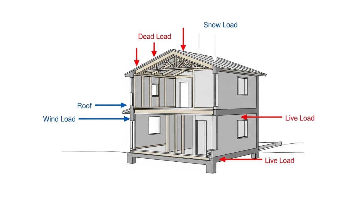
To design any safe structure, we must first categorize the forces it will encounter during its operational lifetime. These forces are broadly split into gravity (vertical) loads and lateral (horizontal) loads. Gravity loads pull downward due to the earth’s gravitational field, while lateral loads push sideways, often caused by wind, seismic activity, or soil pressure.
1. Dead Loads (D): The Permanent Footprint
Dead loads represent the permanent, static weights of the structural elements themselves and any permanently attached fixtures. This includes columns, beams, slabs, walls, roofing, plumbing, HVAC ducts, and architectural finishes.
To calculate the dead load of a structural member, we use the material’s density and its volume. The basic formula is:
For example, if you are designing a reinforced concrete slab that is 8 inches (0.67 feet) thick, and concrete has a typical unit weight of 150 pounds per cubic foot (pcf), the dead load per square foot is calculated as:
2. Live Loads (L): The Transient Occupancy
Live loads are temporary, transient forces produced by the use and occupancy of the building. They include people, furniture, vehicles, and stored materials. Unlike dead loads, live loads are variable in both magnitude and location.
Structural engineers do not guess these values. Instead, we refer to codes like ASCE 7-22 or the International Building Code (IBC), which prescribe minimum design live loads based on the occupancy type.
Under certain conditions, codes allow for a “Live Load Reduction” for members supporting large tributary areas. The reduction formula under ASCE 7 is:
Where:
• L = Reduced design live load per square foot.
• L_0 = Unreduced nominal live load.
• K_LL = Live load element factor (e.g., 4 for interior columns).
• A_T = Tributary area in square feet.
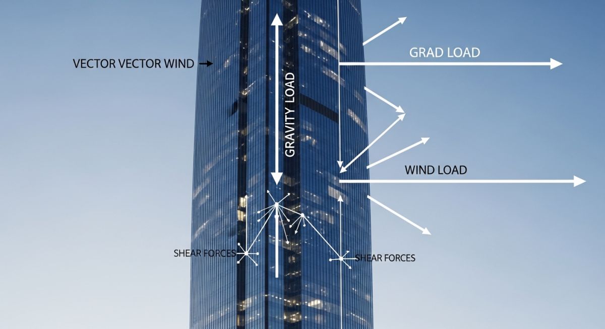
3. Wind Loads (W): Dynamic Lateral Pressures
Wind loads are lateral forces exerted by kinetic energy from moving air masses. As wind hits a structure, it creates positive pressure on the windward face and negative pressure (suction) on the leeward face and roof.
The basic velocity pressure equation used in wind design is:
Where:
• V = Basic wind speed (mph).
• K_z = Velocity pressure exposure coefficient.
• K_zt = Topographic factor.
• K_d = Wind directionality factor.
• K_e = Ground elevation factor.
4. Seismic Loads (E): Inertial Ground Acceleration
Seismic loads are not applied directly to a structure by external contact. Instead, they are inertial forces generated by ground acceleration during an earthquake. As the ground moves rapidly back and forth, the mass of the building resists this movement due to inertia.
The Equivalent Lateral Force (ELF) procedure is a common method used to calculate the seismic base shear (V):
Where:
• C_s = Seismic response coefficient (based on soil type, seismic design category, and building ductility).
• W = Effective seismic weight of the structure (which includes 100% of dead loads and a percentage of permanent storage/snow loads).
Design load values: The standardized minimum design loads for buildings and other structures specified by ASCE 7-22 to prevent structural failure.
Below is a reference table outlining the standard minimum uniformly distributed live loads for common occupancies. These values represent the baseline requirements before applying any reductions.
| Occupancy / Use Category | Uniform Live Load (psf) | Uniform Live Load (kN/m²) | ASCE 7-22 Reference Section |
|---|---|---|---|
| Residential (Apartments, Private Rooms) | 40 | 1.92 | Table 4.3-1 |
| Office Buildings (Standard Offices) | 50 | 2.40 | Table 4.3-1 |
| Office Buildings (Lobbies / Corridors) | 100 | 4.79 | Table 4.3-1 |
| Light Storage Warehouses | 125 | 5.99 | Table 4.3-1 |
| Heavy Storage Warehouses | 250 | 11.97 | Table 4.3-1 |
This matrix maps the core technical entities, structural acronyms, physical parameters, and hyperlinked standard references used in modern structural load calculations.
| Entity / Acronym | Full Technical Name | Primary Physical Parameter | Governing Standard Reference |
|---|---|---|---|
| ASD | Allowable Strength Design | Serviceability & Elastic Limits | AISC 360 |
| LRFD | Load and Resistance Factor Design | Ultimate Strength Limits | ACI 318 |
| ELF | Equivalent Lateral Force | Seismic Base Shear (V) | ASCE 7 Chapter 12 |
| MWFRS | Main Wind Force Resisting System | Global Wind Pressures | ASCE 7 Chapters 26-28 |
Site load verification: The field inspection protocol used to validate that actual structural materials and equipment weights do not exceed design assumptions.
In my experience, discrepancies between design drawings and actual field conditions are a common source of structural issues. Use this checklist on your job site to verify that the loads applied to your structure match the design calculations.
Field Load Verification Checklist
-
Material Density Check: Verify that the concrete mix design and aggregate type match the specified unit weight (e.g., 145 pcf for plain concrete, 150 pcf for reinforced concrete).
-
Architectural Finishes: Confirm that the thickness of floor screeds, tiling, and ceiling systems does not exceed the allowance allocated in the dead load budget.
-
Equipment Weight Certification: Obtain certified vendor drawings for all heavy mechanical, electrical, and piping equipment to verify operating and empty weights.
-
Construction Surcharge Limits: Ensure that temporary construction loads, such as concrete formwork, shoring, and material staging, do not exceed the design live load capacity of the green concrete slabs.
-
Cladding and Facade Weights: Cross-reference the weight of curtain walls or precast concrete panels with the structural framing design assumptions.
Field Case Study: Real-World Application
The Problem: Overloaded Industrial Mezzanine
During a routine facility audit at a chemical processing plant, I discovered that a steel mezzanine originally designed for a light storage live load of 125 psf had been repurposed. The plant operators had installed three heavy chemical dosing pumps and a localized piping manifold directly on the center of the bay.
The combined static weight of the equipment, fluid contents, and localized piping vibration created a concentrated load equivalent to 280 psf. This was more than double the original design limit. The primary support beams were showing visible mid-span deflection, and the connection bolts were experiencing high shear stress.
The Outcome: Retrofitting and Load Redistribution
We immediately implemented temporary shoring beneath the mezzanine to stabilize the structure. To resolve the issue permanently without shutting down plant operations, we designed a localized steel grillage system. This grillage redistributed the heavy equipment loads directly to the main building columns, bypassing the weak floor deck.
We also reinforced the existing steel beams by welding structural steel channels to their bottom flanges, increasing their section modulus. This field intervention successfully restored the required safety factors under AISC 360 standards without requiring a costly structural rebuild.
My recommendation for any facility manager or field engineer is simple: always maintain an updated structural load map of your facility. Before placing any new equipment, verify the existing capacity with a qualified structural engineer.
Frequently Asked Engineering Questions
What is the difference between Dead Load and Live Load?
How do environmental loads differ from gravity loads?
Why are load combinations necessary in structural design?
What is the difference between ASD and LRFD design methods?
How does wind load affect high-rise buildings compared to low-rise buildings?
What are dynamic loads and when must they be considered?

📚 Recommended Resources: types of loads on structures
Read these Guides


Related posts:
![A split-view illustration showing the transition from traditional refinery infrastructure to modern sustainable aviation fuel production facilities at an airport.]()
Sustainable Aviation Fuel Explained: Engineering Pathways for Global Decarbonization
![3D engineering visualization of a green hydrogen production facility showing electrolyzers, renewable energy integration, and storage infrastructure.]()
Levelized Cost of Hydrogen: Engineering Economics for Industrial Decarbonization
![Industrial schematic showing renewable electricity integration into an RFNBO hydrogen production facility for regulatory compliance.]()
RFNBO Explained: Complete Guide for Engineers and Project Developers
![Industrial facility undergoing a green energy retrofit with new hydrogen-ready piping infrastructure and renewable energy integration.]()
RED III Explained: Everything Engineers Need to Know for Compliance
![Conceptual diagram of renewable energy sources feeding a green hydrogen electrolysis plant under RFNBO compliance.]()
Additionality Explained Under RFNBO Rules: A Technical Engineering Perspective
![Conceptual visualization of temporal correlation between wind energy generation and green hydrogen electrolysis for EU regulatory compliance.]()
Temporal Correlation Explained Under RFNBO Regulations